Table of Contents
Advertisement
Quick Links
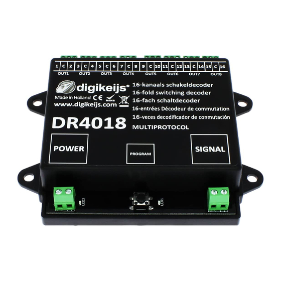
DR4018 DIGISWITCH (v1.2)
DR4018
DIGISWITCH
HANDLEIDING / MANUAL
BEDIENUNGSANLEITUNG / MANUEL
V1.2
(05-02-2012)
© Copyright 2005 – 2012 digirails, the Netherlands. All rights re-
served. No information, images or any part of this document
may be copied without the prior written permission of Digirails.
www.digirails.com
Page 1
Advertisement
Table of Contents

Related Manuals for digirails DIGISWITCH DR4018

Summary of Contents for digirails DIGISWITCH DR4018
- Page 1 HANDLEIDING / MANUAL BEDIENUNGSANLEITUNG / MANUEL V1.2 (05-02-2012) © Copyright 2005 – 2012 digirails, the Netherlands. All rights re- served. No information, images or any part of this document may be copied without the prior written permission of Digirails. www.digirails.com...
-
Page 2: Product Description
Intellibox DCC / Motorola Intellibox Basic DCC / Motorola Intellibox II DCC / Motorola Marklin 6021 Motorola Marklin CS1 Motorola ROCO/Fleischmann Multimaus ROCO/Fleischmann MultimausPRO LENZ Tams Easy control DCC / Motorola ESU ECOS DCC / Motorola www.digirails.com Page 2... -
Page 3: Quick Start
Disconnect both the power and the signal inputs and wait for 3 to 5 seconds. Step 10: The decoder can now be reconnected to the power and will have returned to the factory settings. BE CAREFUL! The decoder now has address 1 again. www.digirails.com Page 3... - Page 4 The module is ready for immediate use with the modified settings. BE CAREFUL! In some cases the DR4018 must be given a new address by following the steps in the ‘Give the mo- dule an address’ section on page 3 of this manual. www.digirails.com Page 4...
- Page 5 PWM Period The resolution with which the internal PWM operates to achieve effects and dim-values 1-255 Fade Speed The speed with which the outputs configured for fading will fade in and fade out 1-255 Blink rate The speed with which the outputs configured for blinking will blink 1-255 www.digirails.com Page 5...
- Page 6 DB_HP (German main signal) DB_VRHP (German front and main signal) DB_VR (German front signal) NMBS (Belgium railways) Signal 2, configuration OUT 5 - 8 Signal 3, configuration OUT 9 - 12 Signal 4, configuration OUT 13 - 16 www.digirails.com Page 6...
- Page 7 Key 14 Key 15 Key 16 * The RED numbers are the standard factory settings for GROUP A (1 through 8) * The ORANGE numbers are the standard factory settings for GROUP B ( 9 through 16 ) www.digirails.com Page 7...
-
Page 8: Output Pulse Times
Flash double yellow Yellow with digit Green yellow horiz. Flashing green Green Flashing yellow Flashing green Yellow with flashing digit Green yellow vertical R = Red button on your control unit G = Green button on your control unit www.digirails.com Page 8... -
Page 9: Frequently Asked Questions
When programming / reading the CV, my unit shows “error”. What’s going on? The decoder has a power buffer for switching coil actuators, which has to be loaded first. Try reading / programming again (several times if necessary) EXTERNAL FEED FEED FROM CONTROL UNIT www.digirails.com Page 9... - Page 10 DR4018 DIGISWITCH (v1.2) Preset connection examples Points motor with cut-out Points motor without cut-out 0 1 2 3 6 13 DR4103 CONNECTION TL GROUP A TL GROUP B 1x 16 TL GROUP www.digirails.com Page 10...
- Page 11 PRESET 1 - SWITCH DECODER This preset makes the module a 16-channel switch decoder and assigns every output its own address. Each output can be switched individually allowing you, for example, to control the lighting on your model railway. Connection example: www.digirails.com Page 11...
- Page 12 0-255 Pulse time OUTPUT 11 0-255 OUT 6 Pulse time OUTPUT 12 0-255 Pulse time OUTPUT 13 0-255 OUT 7 Pulse time OUTPUT 14 0-255 Pulse time OUTPUT 15 0-255 OUT 8 Pulse time OUTPUT 16 0-255 www.digirails.com Page 12...
- Page 13 2 GROUPS of 8 FLOURESCENT TUBE EFFECTS or 1 GROUP with 16 FLOURESCENT TUBE EFFECTS This preset sets the module to switch 16 lights with the well-known fluorescent blinking effect. TL GROUP A TL GROUP B 1x 16 TL GROUP www.digirails.com Page 13...
- Page 14 R = Red button on your control unit (In software programs such as Koploper, R is -> turning off) G = Green button on your control unit (In software programs such as Koploper, G is -> straight on) www.digirails.com Page 14...
- Page 15 This preset sets the module to be a signal decoder that can be used to switch 4 German pre-signals. Connection example: PRESET 10: 2x Combination of DB MAIN SIGNAL with PRE-SIGNAL This preset sets the module to be a signal decoder that can be used to switch 2 German combi signals. Connection example: www.digirails.com Page 15...
- Page 16 This preset sets the module to be a signal decoder that can be used to switch 4 German separate pre-signals. Connection example: PRESET 12: 4x NMBS Signal This preset sets the module to be a signal decoder that can be used to switch 4 Belgian main signals. Connection example: www.digirails.com Page 16...
-
Page 17: Connection Example
(Address 15 OFF, Output 1 through 8) CV231 -> (Address 16 ON, Output 9 through 16) CV232 -> (Address 16 ON, Output 9 through 16) CV234 -> (Address 16 OFF, Output 1 through 8) CV235 -> (Address 16 OFF, Output 9 through 16) www.digirails.com Page 17...
Need help?
Do you have a question about the DIGISWITCH DR4018 and is the answer not in the manual?
Questions and answers