Advertisement
Table of Contents
Advertisement
Table of Contents

Subscribe to Our Youtube Channel
Summary of Contents for desmon PH8
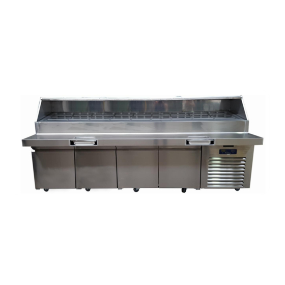
- Page 1 Pizza Hut Make Table Operating and Service Manual...
-
Page 2: Table Of Contents
#Pizza Hut Make Table operating and service manual Table of content 1. Specification 2. Serial tag 3. Safety instructions 4. General description, zones and main component identification 7-10 5. Installation 11-12 6. Power on 13-14 7. Switch On-Off 14-15 8. Routine maintenance 16-17 9. -
Page 3: Specification
#Pizza Hut Make Table operating and service manual Specification Model Temp.°F Door Capacity Dimensions Voltage Amps �� type Charge Lt/���� 28°/46°F 840/30 115/60/1 R404A 70.6 96” 42” 56” Model Temp.°F Door Capacity Dimensions Voltage Amps �� Lt/���� type Charge PH10 28°/46°F 840/30 115/60/1... -
Page 4: Serial Tag
#Pizza Hut Make Table operating and service manual 2. Serial tag The serial tag is permanently affixed label on which is recorded the vital electrical and refrigeration data about the unit, such as the model, the serial number, year and month production, voltage, total absorbed power, type and charge of refrigerant. -
Page 5: Safety Instructions
Before any maintenance work is performed, the appliance must be disconnected from the electrical supply. Apply a lockout tag to the electrical supply connection. All replacement parts that are not supplied by Desmon must be pre- approved before installation... - Page 6 #Pizza Hut Make Table operating and service manual Desmon’s approved distributors or one of its authorized representatives must only perform repair work. Desmon accepts no responsibility for any situation resulting from work performed by untrained and/or unauthorized technicians.
-
Page 7: General Description, Zones And Main Component Identification
#Pizza Hut Make Table operating and service manual 4. General description, zones main component identification RAIL COMPARTMENT* COOLING SYSTEM Ventilated, with evaporator fans Hot Gas Defrost, Auto Defrost function with DEFROST TYPE Manual Defrost option Drainage plug on right side of the pan DRAINAGE SYSTEM compartment. - Page 8 #Pizza Hut Make Table operating and service manual Evaporator coil Evaporator tray Undercounter compartment Magnetic front panel (Double Eliwell version) Controller compartment A (Undercounter) Controller compartment B (Condiment rail) Drainage hose Condenser coil Condenser coil...
- Page 9 #Pizza Hut Make Table operating and service manual Removable magnetic door gasket Condiment rail hinged top section Removable interior structure Main switch holding pans Motor compartment Condenser fan Electrical box...
- Page 10 #Pizza Hut Make Table operating and service manual Condiment rail Hot gas valve Pressure switch Compressor Under counter Drainage tray Liquid receiver Filter dryer Compartment B Pump down valve (Condiment rail) Compartment A Pump down valve (Under counter) Compartment A TX valve (Under counter) Compartment B...
-
Page 11: Installation
#Pizza Hut Make Table operating and service manual 5. Installation Minimum clearances, distances, and spacing’s for installation. 20 cm 20 cm (8”) (8”) FRONT VIEW 20 cm (8”) SIDE VIEW... - Page 12 #Pizza Hut Make Table operating and service manual 5.1 Work plan Installation The work plan of the PH models uses to be delivered disassembled. In order to start operation, put the work plan on the top of the under counter and slip it up to the fixing position.
-
Page 13: Power On
#Pizza Hut Make Table operating and service manual 6. Power ON This equipement is provided with an insulated power cord but no plug therefore before starting operation clamp the plug to the power cord and then connect it to main power supply. -
Page 14: Switch On-Off
#Pizza Hut Make Table operating and service manual The temperature values shown in the above displays are only an example. In a real situation at the start up the controllers will show the ambient temperature, if the unit has been not operating previously. - Page 15 #Pizza Hut Make Table operating and service manual 2) One or both display will light up and show “OFF” Press and hold for 5 seconds the ON/OFF key to switch the controller ON. Press & Hold 3) No display lights on. Remove the front panel to access the Main Switch.
-
Page 16: Routine Maintenance
#Pizza Hut Make Table operating and service manual Routine maintenance DISCONNECT THE UNIT FROM THE POWER SOURCE WHENEVER PERFORMING SERVICE/MAINTENANCE FUNCTION AND/OR CLEANING THE REFRIGERATED AREA Clean the under counter and the external surfaces Disconnect the power cord (or alternatively set the main switch to OFF). Use a mild detergent, water, and wipe the gaskets. - Page 17 #Pizza Hut Make Table operating and service manual Remove and clean the honeycomb It’s recommended a weekly honeycomb cleaning. Remove the stain steel liner of the interior of the condiment rail and then remove the honeycomb holder. Unfasten the screw that fix up the honeycomb and take it apart.
-
Page 18: Cooling Unit Scheme
#Pizza Hut Make Table operating and service manual 9. Cooling units scheme ELECTRICAL COMPONENT INSTALLED • COMPRESSOR • CONDENSER FAN • SOLENOID VALVE A • SOLENOID VALVE B • HOT GAS VALVE B • EVAPORATOR FAN A • EVAPORATOR FAN B •... -
Page 19: Sequential Function
#Pizza Hut Make Table operating and service manual Sequencial functions 1) POWER ON (BOTH COMPARTMENTS NEED COOLING) CONTROLLER B CONTROLLER A As soon as Pan and Counter Compartments start asking cooling to the system (in the instance that the inner temperatures are higher than the set point), there is 1 minute delay during which the cooling LED will blink. - Page 20 #Pizza Hut Make Table operating and service manual 2) RUNNING CONFIGURATION AFTER 1° MINUTE DELAY Assuming that temperatures in both compartments are higher than the set point, both A and B valves will open to circulate refrigerant in the respective cooling circuits. Opening the two valves will increase the suction pressure above 0 bar + differential, thus allowing the pressure switch to close the circuit and engage compressor.
- Page 21 #Pizza Hut Make Table operating and service manual 3) EVAPORATOR FAN TURN ON As soon as evaporator coil reaches a proper temperature, the evaporator fans will cut-in. FAN LED CIRCUIT A COUNTER CIRCUIT B PAN COOLER...
- Page 22 #Pizza Hut Make Table operating and service manual 4) ONE OUT OF THE TWO COMPARTMENTS HAVE REACHED THE SET POINT TEMPERATURE (FOR INSTANCE COUNTER) Solenoid valve A will de-energize and refrigerant will keep circulating only in circuit B (Pan Rail). Note that the FAN LED on controller A is turned off. B CONTROLLER A CONTROLLER CIRCUIT B...
- Page 23 #Pizza Hut Make Table operating and service manual 5) BOTH COMPARTMENTS HAVE REACHED THE SET POINT TEMPERATURE Both solenoid valves will close. Compressor will still run in a “pump-down” configuration, sucking the entire refrigerant from the evaporating circuits and pushing it into the liquid receiver.
- Page 24 #Pizza Hut Make Table operating and service manual 6) PRESSURE SWITCH OPENS As the compressor is still running while valves A and B are closed, the suction pressure will gradually decrease until reaching to 0.10 PSI, thus causing the pressure switch to open and cut off both compressor and condenser fan.
-
Page 25: Wiring Diagram
Wiring scheme Pizza Hut Make table operating and service manual...
Need help?
Do you have a question about the PH8 and is the answer not in the manual?
Questions and answers
My supervisor have us turn this device off every night to supposedly to prevent ice buildup, I personally think that’s had on the machine