Table of Contents
Advertisement
Quick Links
12VDC
DRY LOCATION
SAFETY & WARNINGS
READ AND FOLLOW ALL SAFETY INSTRUCTIONS
1. Install in accordance with national and local electrical code
regulations.
2. This product is intended to be installed and serviced by a
qualified, licensed electrician.
3. Do not modify or disassemble this product beyond instructions
or the warranty will be void.
4. Do not use if there is any damage to the fixture or wiring.
Inspect periodically.
5. Do not submerge PowerTrax
the vicinity of standing water or other liquids.
6. All plastics are affected by the elements and may shift in color
and other properties after product installation, particularly with
direct exposure to sun.
7. Do not attempt to fix this product in the field.
8. Failure to follow safety warnings, and installation instructions
will void the warranty for this product.
Installation GUIDE
POWERTRAX
™
®
24VDC
in liquids or use the product in
™
POWERTRAX
QUICK SPECS / MODELS
Max Amperage
Environment*
*NOT FOR USE IN SUBMERSIBLE APPLICATIONS, OR
WITHIN 5 FEET OF A SWIMMING POOL.
REQUIRED TOOLS
1
1. Phillips-head Screwdriver
2. Ruler (Recommended)
3. Screws (Appropriate for surface being installed on)
1 OF 4
SYSTEM
™
INSTALLATION GUIDE
12V - 5A
24V - 4A
Indoor Location
3
2
IG111319-1.0
Advertisement
Table of Contents

Summary of Contents for DIODE LED PowerTRAX
- Page 1 REQUIRED TOOLS 4. Do not use if there is any damage to the fixture or wiring. Inspect periodically. 5. Do not submerge PowerTrax in liquids or use the product in ™ the vicinity of standing water or other liquids.
- Page 2 HOW MANY MODULES CAN BE ATTACHED? Option B: Fasten track to surface utilizing correct screws. Up to 15 may be attached. Do not to exceed maximum amperage (12V - 5A, 24V - 4A) of PowerTRAX system. ™ INSTALLATION GUIDE POWERTRAX 2 OF 4 IG111319-1.0...
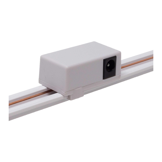
- Page 3 POWERTRAX SYSTEM ™ INSTALLATION GUIDE INSTALLATION (Cont.) CONNECT POWER & LIGHT ENGINE Connect power and light engine to modules using male DC barrel plugs.* Connections facing in opposite direction will not function. Male DC barrel plug IMPORTANT: Ensure all module connections are facing same direction.
- Page 4 POWERTRAX SYSTEM ™ INSTALLATION GUIDE TOOLS & RESOURCES INSTALLATION (Cont.) POWERTRAX SPECIFICATION SHEET ™ For full specifications. TURN POWER ON AT CIRCUIT BREAKER SYSTEM DIAGRAMS Traditional ON/OFF System Inline On/Off Switch or Dimmer System Class 2 Class 2 Plug-In Adapter...
Need help?
Do you have a question about the PowerTRAX and is the answer not in the manual?
Questions and answers