
Summary of Contents for Vanderbilt GMYA7-AS
- Page 1 GMYA7-AS GMYA7-A GMYA7-S Remote testing system for seismic detectors Fernprüfsystem für Körperschallmelder Vanderbilt A6V10200077_e 08.02.2016...
- Page 2 Copyri ght Technical specifications and availability subject to change without notice. © Vanderbilt 2015. We reserve all rights in this document and in the subject thereof. By acceptance of the document the recipient acknowledges these rights and undertakes not to publish the document nor the subject thereof in full or in part, nor to make them available to any third party without our prior express written authorization, nor to use it for any purpose other than for which it was delivered to him.
-
Page 3: Table Of Contents
Beschreibung Anwendung ............................. 25 Voraussetzungen für einen sicheren Einsatz ................. 25 Lieferumfang Montage und Installation Abbildung 1: Anschlüsse bei geöffnetem Gehäuse ................ 26 Hinweise zur Montage ........................26 Abbildung 2: Verbindung der Gehäuse ..................27 Vanderbilt A6V10200077_e Installation Instructions 08.02.2016... - Page 4 6.1.2 Anzeigemodul ..........................36 Abbildung 6: Anzeigemodul ......................36 6.2.1 Anzeigemodul schalten........................36 6.2.2 Wartung Service ............................37 Schließzylinder austauschen ......................37 Typenschild ............................. 37 Gewährleistung / Garantie Störungen Technische Daten Bestellinformationen Ursache und Wirkung Vanderbilt A6V10200077_e Installation Instructions 08.02.2016...
-
Page 5: Ec Declaration Of Conformity
1 EC declaration of conformity Hereby Vanderbilt International (IRL) Ltd declares that this equipment type is in compliance with all relevant EU Directives for CE marking. From 20/04/2016 it is in compliance with Directive 2014/30/EU (Electromagnetic Compatibility Directive). The full text of the EU declaration of conformity is available at the following internet address: http://pcd.vanderbiltindustries.com/doc/Seismic. -
Page 6: Application
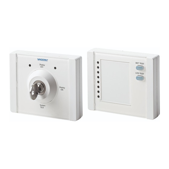
The remote testing system must be connected to a source of voltage with a limited rating in accordance with EN60950-1. 4 Scope of supply Basic module GMYA7-AS Indicator module GMYA7-A (optional) 1 x Key module with 2 keys 1 x Indicator module... -
Page 7: Assembly And Installation
4. Modules should preferably be joined together on the long side. Use the mounting aid (Fig.1, item F) for this purpose. If modules are to be connected on the short side, at least two pairs of modules should be con- nected next to one another on this side. Vanderbilt A6V10200077_e Installation Instructions... - Page 8 Inner view of GMYA7 housing Snap-in hook Printed circuit board Screw terminal Tamper contact switch Mounting screw for printed circuit board Retaining clips Holes for mounting Safety screw for back tamper con- tact Break-out point for cable entry Vanderbilt A6V10200077_e Installation Instructions 08.02.2016...
- Page 9 Snap the mounting aid into the pins on the back of the housing. 5. Make the holes for the housing fastening (Fig. 2, Inner view of GMYA7-AS housing, item I) and safety screw (Fig. 2, Inner view of GMYA7-AS housing, item J).
-
Page 10: Connection Assignment
4 conductors per terminal). KSM_6 IN Connect the EL Alarm(12) alarm outputs of the individual seismic detectors to KSM_5 IN KSM_0 IN… KSM_7 IN. KSM_4 IN KSM_3 IN KSM_2 IN KSM_1 IN KSM_0 IN Vanderbilt A6V10200077_e Installation Instructions 08.02.2016... - Page 11 Connection assignment between SPARE modules - connection on key mod- ule (GMYA7-S to GMYA7-A) STATUS (1) STATUS (0) TAMPER B TAMPER A KEY STATE (1) KEY STATE (0) DAY NIGHT + 12V IN 0V IN Vanderbilt A6V10200077_e Installation Instructions 08.02.2016...
-
Page 12: Tamper Connections
B – Jumper OFF C – Jumper ON A – Tamper B – Jumper OFF GMYA7-S GMYA7-A GMYA7-A C – Jumper ON 9. Set the jumper on the last indicator module to ON, all other jumpers are OFF Vanderbilt A6V10200077_e Installation Instructions 08.02.2016... -
Page 13: Configure The Key Module
Day/night input: Set the polarity with the DIP switch. Active high = 0 V applied Active low = 0 V removed Function according to VdS Inverted Night = Active high Night = Active low (0 V) Vanderbilt A6V10200077_e Installation Instructions 08.02.2016... -
Page 14: Configure The Indicator Module
14. Carry out initial commissioning as described in the Operation section. Once successfully commissioned, the remote testing system is operational and can be sealed. We would recom- mend taking a log of commissioning, using the GMSW7 SensTool software. Vanderbilt A6V10200077_e Installation Instructions... -
Page 15: Operation
To switch off, turn the key to Display OFF and remove the key. Fault Fault in indicator module or key mod- ule. (see "Faults" chapter) Insert key in Display OFF The remote testing system is ready. position (Fig. 5, item E) The displays are off. Vanderbilt A6V10200077_e Installation Instructions 08.02.2016... - Page 16 After 5 seconds New test is carried out on all indicator modules. (LED lights up constantly) Orange Test result appears in the indicator module. LED lights up constantly if the seismic detector is functioning correctly. Vanderbilt A6V10200077_e Installation Instructions 08.02.2016...
-
Page 17: Indicator Module
2002/96/EC (WEEE) and must not be disposed of with domestic waste. The device should be dis- posed of via the intended channels. Local legislation and that valid at the time must be taken into ac- count. Vanderbilt A6V10200077_e Installation Instructions... -
Page 18: Service
Service Vanderbilt provides service around the world. Contact www.service.vanderbiltindustries.com. Replacing locking cylinders When replacing, we would recommend using a KESO universal cylinder type 23.008.025 or KABA 1008c. 1. Open housing (see Assembly). 2. Remove key. 3. Use screwdriver to remove 2 flat head screws on cylinder driver. -
Page 19: Warranty / Guarantee
8 Warranty / Guarantee Vanderbilt only supplies tested products. Should the product or packaging be defective despite these checks, the following details are needed for complaints: Type Item number (see type plate) Week code Product version ... -
Page 20: Details For Ordering
11 Details for ordering V54534-F101-A100 Remote testing system for seismic detectors (type: GMYA7-AS) V54534-F102-A100 Alarm for indicator module (type: GMYA7-A) VA5Q00006246 SensTool Software V54534-F109-A100 GM775 Seismic detector VBPZ:4202370001 GMXS1 Internal Test transmitter 12 Cause and effect Cause System GMA7-S Key... - Page 21 Display On Unset First detector pulsing, next detector(s) con- stant Display On First detector pulsing, Clear alerts from next detector(s) con- panel, clears stored stant alarms from memory Unset Display On Setting system clears all stored alarms Vanderbilt. A6V10200077_e Installationsanweisungen 08.02.2016...
- Page 22 Technische Spezifikationen und Verfügbarkeit können ohne vorherige Ankündigung geändert werden. © Vanderbilt 2015. Wir behalten uns alle Rechte an diesem Dokument und an dem in ihm dargestellten Gegenstand vor. Der Emp- fänger anerkennt diese Rechte und wird dieses Dokument nicht ohne unsere vorgängige schriftliche Ermächti- gung ganz oder teilweise Dritten zugänglich machen oder zu einem anderen Zweck verwenden als dem, zu dem...
- Page 23 6.1.2 Anzeigemodul ..........................36 Abbildung 6: Anzeigemodul ......................36 6.2.1 Anzeigemodul schalten ........................36 6.2.2 Wartung Service ............................37 Schließzylinder austauschen ......................37 Typenschild ............................. 37 Gewährleistung / Garantie Störungen Technische Daten Bestellinformationen Ursache und Wirkung Vanderbilt. A6V10200077_e Installationsanweisungen 08.02.2016...
-
Page 24: Eg-Konformitätserklärung
EG-Konformitätserklärung Hiermit erklärt Vanderbilt International (IRL) Ltd, dass dieser Gerätetyp den Anforderungen aller relevanten EU- Richtlinien für die CE-Kennzeichnung entspricht. Ab dem 20.04.2016 entspricht er der Richtlinie 2014/30/EU (Richtlinie über elektromagnetische Verträglichkeit). Der vollständige Text der EU-Konformitätserklärung steht unter folgender Internetadresse zur Verfügung: http://pcd.vanderbiltindustries.com/doc/Seismic. -
Page 25: Anwendung
GMXS1 ausgerüstet sein. Die Installation des Fernprüfsystems muss fachgerecht erfolgen und nach Erstinbetriebnahme erfolgreich geprüft werden. Das Fernprüfsystem muss an eine Spannungsquelle mit Leistungsbegrenzung nach EN60950-1 angeschlossen sein. Lieferumfang Grundmodul GMYA7-AS Anzeigemodul GMYA7-A (optional) 1 x Schlüsselmodul mit 2 Schlüsseln 1 x Anzeigemodul 1 x Anzeigemodul... -
Page 26: Montage Und Installation
18. Module sind vorzugsweise an der langen Seite zusammen zu fügen. Hierzu ist die Montagehilfe (Abb. 1, Teil F) zu verwenden. Sollen Module an der kurzen Seite verbunden werden, sollten mindestens zwei Modul- paare nebeneinander an der kurzen Seite verbunden werden. Vanderbilt. A6V10200077_e Installationsanweisungen... -
Page 27: Abbildung 2: Verbindung Der Gehäuse
Schnapphaken einrasten. Schrauben anziehen und Plomben (B) anbringen, um die Montage abzuschlie- ßen. Innenansicht des GMYA7-Gehäuses Schnapphaken Leiterplatte Schraubklemme Sabotagekontaktschalter (Tamper) Befestigungsschraube für Leiter- platte Halterungsclips Löcher für Befestigung Sicherungsschraube für Abreiß- kontakt Ausbruchstelle für Kabeleinfüh- rung Vanderbilt. A6V10200077_e Installationsanweisungen 08.02.2016... -
Page 28: Abbildung 3: Zusammenbau Der Montagehilfe
Bei der langen Seite sollten die Markierungen (V) an der Rückseite nebeneinander liegen. Die Montagehilfe in die Stifte auf der Gehäuserückseite einrasten. 19. Die Löcher für die Gehäusebefestigung (Abb. 2, Innenansicht des GMYA7-AS-Gehäuses, Teil I) und die Si- cherheitsschraube (Abb. 2, Innenansicht des GMYA7-AS-Gehäuses, Teil J) bohren. -
Page 29: Anschlussbelegung
ßen (Mehrfachbenutzung, maximal 4 Leiter KSM_6 IN pro Klemme). Die Alarmausgänge "EL Alarm(12) "der einzelnen Körperschallmel- KSM_5 IN der an "KSM_0 IN… KSM_7 IN" anschlie- ßen. KSM_4 IN KSM_3 IN KSM_2 IN KSM_1 IN KSM_0 IN Vanderbilt. A6V10200077_e Installationsanweisungen 08.02.2016... - Page 30 Flachkabelanschlüsse (X1 Klemmleiste) Klemmleiste) Anschlussbelegung für Verbindung RESERVE zwischen Modulen - Anschluss am Schlüsselmodul (GMYA7-S an STATUS (1) GMYA7-A) STATUS (0) SABOTAGE B SABOTAGE A SCHLÜSSELSTA- TUS (1) SCHLÜSSELSTA- TUS (0) TAG NACHT + 12V IN 0V IN Vanderbilt. A6V10200077_e Installationsanweisungen 08.02.2016...
-
Page 31: Sabotageanschlüsse
B – Jumper OFF C – Jumper ON A – Sabotage B – Jumper OFF GMYA7-S GMYA7-A GMYA7-A C – Jumper ON 23. Den Jumper des letzten Anzeigemoduls auf "ON" stellen, alle anderen Jumper auf "OFF". Vanderbilt. A6V10200077_e Installationsanweisungen 08.02.2016... -
Page 32: Schlüsselmodul Konfigurieren
C – DIP-Schalter Tag/Nacht-Eingang: Die Polarität mit dem DIP-Schalter einstellen. Active high = 0 V angelegt Active low = 0 V entfernt Funktion nach VdS Invertiert Nacht = Active high Nacht = Active low (0 V) Vanderbilt. A6V10200077_e Installationsanweisungen 08.02.2016... -
Page 33: Anzeigemodul Konfigurieren
27. Alle Anzeigemodule schließen, dann das Schlüsselschaltermodul schließen, um das System zum ersten Mal einzuschalten. 28. Erstinbetriebnahme entsprechend Abschnitt Betrieb durchführen. Nach erfolgreicher Inbetriebnahme ist das Fernprüfsystem einsatzfähig und kann plombiert werden. Es wird empfohlen, diese Inbetriebnahme mit der Software GMSW7 SensTool zu protokollieren. Vanderbilt. A6V10200077_e Installationsanweisungen 08.02.2016... -
Page 34: Betrieb
Schlüssel einstecken (Abb. 5, Teil H). Das Fernprüfsystem ist betriebsbereit. Zum Ausschalten Schlüssel auf "Display OFF" stellen und Schlüssel abziehen. Störung Störung in Anzeigemodul oder Schlüs- selmodul (siehe Kapitel "Störungen"). Schlüssel in der Stellung Das Fernprüfsystem ist betriebsbereit. "Display OFF" einstecken. Die Anzeigen sind aus. Vanderbilt. A6V10200077_e Installationsanweisungen 08.02.2016... - Page 35 Nach 3 Sekunden Alarmspeicher wird gelöscht. (LED blinkt schnell) Orange Nach 5 Sekunden Neue Prüfung wird bei allen Anzeige- modulen ausgeführt. (LED leuchtet konstant) Orange Prüfergebnis erscheint im Anzeigemo- dul. LED leuchtet konstant bei korrekter Funktion der Körperschallmelder. Vanderbilt. A6V10200077_e Installationsanweisungen 08.02.2016...
-
Page 36: Anzeigemodul
Das Gerät gilt für die Entsorgung als Elektronik-Altgerät im Sinne der Europäischen Richtlinie 2002/96/EG (WEEE) und darf nicht als Haushaltsmüll entsorgt werden. Das Gerät ist über die dazu vorgesehenen Kanäle zu entsorgen. Die örtliche und aktuell gültige Gesetzgebung ist zu beachten. Vanderbilt. A6V10200077_e Installationsanweisungen... -
Page 37: Service
Service Vanderbilt bietet weltweiten Service an. Kontakt www.service.vanderbiltindustries.com. Schließzylinder austauschen Zum Austausch wird empfohlen, einen KESO Universalzylinder Typ 23.008.025 oder KABA 1008c zu verwen- den. 12. Gehäuse öffnen (siehe Montage). 13. Schlüssel abziehen. 14. 2 Senkschrauben am Zylindermitnehmer mit Schraubendreher entfernen. -
Page 38: Gewährleistung / Garantie
Gewährleistung / Garantie Vanderbilt liefert nur geprüfte Produkte. Sollten trotzdem Mängel an Produkt oder Verpackung vorhanden sein, müssen zur Reklamation folgende Angaben gemacht werden: Artikelnummer (siehe Typenschild) Wochencode Erzeugnisstand Informationen über Lieferung (Lieferant, Datum usw.) ... -
Page 39: Bestellinformationen
Bestellinformationen V54534-F101-A100 Fernprüfsystem für Körperschallmelder (Typ GMYA7-AS) V54534-F102-A100 Alarm für Anzeigemodul (Typ: GMYA7-A) VA5Q00006246 Software SensTool V54534-F109-A100 Körperschallmelder GM775 VBPZ:4202370001 GMXS1 Prüfsender Ursache und Wirkung Ursache System- GMA7-S GMA7-S LED GMA7-A LEDs 1-8 Bemerkung: status Schlüssel- (Farbe) stellung Scharf Keine Funktion... - Page 40 Ursache System- GMA7-S GMA7-S LED GMA7-A LEDs 1-8 Bemerkung: status Schlüssel- (Farbe) stellung Scharf Anzeige Ein Erster Melder pulsie- rend, nächste/r Melder konstant Unscharf Anzeige Ein Erster Melder pulsie- rend, nächste/r Melder konstant Scharf Anzeige Entfernen der Alarme aus der Zentrale und Ein- stellen, LEDs jetzt Erster Melder...
- Page 44 Issued by: Data and design subject to change Vanderbilt without notice Clonshaugh Business and Technology Park Clonshaugh www.vanderbiltindustries.com Dublin Supply subject to availability D17 KV84 Document no. A6V10200077 Ireland www.service.vanderbiltindustries.com Document version: e...
Need help?
Do you have a question about the GMYA7-AS and is the answer not in the manual?
Questions and answers