Table of Contents
Advertisement
Quick Links
Preface
Thank you for choosing the CHV110 series of injection molding machine energy savers
developed by Shenzhen INVT Electric Co., Ltd..
This operating instruction manual must be made available for actual operators of the
equipment.
To guarantee the safety of users and to achieve the optimal energy saving effect while
satisfying technological requirements of energy savers, please read this operating
instruction manual carefully before use.
CHV110 series energy savers are applicable to various injection molding machines with
constant delivery pumps under hydraulic transmission control. According to different
pressures and rates of flow required for different operational stages of injection molding
machines, the user can adjust the output power of the oil pump accordingly to save
energy by 25% to 50%. They feature high energy conservation ratio, high reliability, motor
soft start, and easy operation.
If you have any problems during use, please contact our technical department.
Please keep this operating instruction manual properly as a reference in future
maintenance, repair, and use in a different operating condition.
The company reserves the right to constantly improve its products. Any technical
improvement, if without impact on the use of the equipment, shall be made without notice.
1
Advertisement
Table of Contents

Related Manuals for INVT CHV110 Series


Summary of Contents for INVT CHV110 Series
- Page 1 Preface Thank you for choosing the CHV110 series of injection molding machine energy savers developed by Shenzhen INVT Electric Co., Ltd.. This operating instruction manual must be made available for actual operators of the equipment. To guarantee the safety of users and to achieve the optimal energy saving effect while satisfying technological requirements of energy savers, please read this operating instruction manual carefully before use.
-
Page 2: Table Of Contents
Table of Contents 1. Energy Saving Principle………………………………………..………………………..1 2. Product Features……………………………………….………..………..……………..2 3. Application Environment………………………………………..…..………….………..3 4. Installation and Configuration………………………………….………………………..4 4.1 Environmental Requirements…………………………….…………………………5 4.2 Outside Dimensions of Energy Saver………………………………………………6 4.3 Connection of Injection Molding Machine with Energy Saver……………………7 4.4 Operation Instructions for Current Signal Acquisition Card…………………….10 Signal Acquisition Method... -
Page 3: Energy Saving Principle
Energy Saving Principle For traditional injection molding machines with constant delivery pumps, valve adjustment is required to change load flow rate and pressure. In this case, input power changes slightly, and a large proportion of energy is consumed by the valve in the form of pressure difference, causing overflow. -
Page 4: Product Features
Product Features CHV110 series of products are the latest products launched by Shenzhen INVT Electric Co.,Ltd. based on its years of experience in research, development, production, and on-site rebuilding of energy savers for injection molding machines. The products represent the leading level in the same industry. Compared with existing product, CHV110 series have the following features: •... -
Page 5: Application Environment
Application Environment To achieve better energy saving effect, the following aspects must be taken into account before carrying out the energy saving rebuilding for injection molding machines: Type of injection molding machine: The energy saver is applicable to injection molding machines with hydraulic constant delivery pumps only, and it is not applicable to other types of injection molding machines (such as those with electric or variable delivery pumps). -
Page 6: Installation And Configuration
Installation and Configuration Safety Instructions Please read this operating instruction manual careful before installing, operating, maintaining or checking the equipment. Safety information in this manual is divided into “WARNING” and “CAUTION”. WARNING Indicates potential hazards that, if not avoided, could result in loss of life or serious injury. -
Page 7: Environmental Requirements
WARNING • Operation on the component/system of the inverter by untrained personnel or nonobservance of requirements stipulated in the warning may result in severe personal injury or property loss. Only qualified personnel who have received training in equipment design, installation, debugging operation work... -
Page 8: Outside Dimensions Of Energy Saver
• The surrounding shall be free of electromagnetic interference and the equipment shall be kept at a distance away from any interference source; • Flammables, thinners and solvents shall be kept far away from the equipment. • The equipment shall be prevented from dust, oily dust, floating fiber, and metallic particles. - Page 9 A (mm) B(mm) C(mm) Model and Power Range Outside Dimensions CHV110-(07R5-015)T3 CHV110-(018-030)T3 CHV110-(037-055)T3 CHV110-075T3 Warning • To ensure safe operation of the inverter, only qualified and service-trained electrician can work on the equipment. • It is strictly forbidden to test the insulation of the cables connected to the inverter with high-voltage insulation testing equipment.
-
Page 10: Connection Of Injection Molding Machine With Energy Saver
• Confirm that the rated voltage of the inverter is consistent with the AC power voltage. • Power cables and motor cables must be connected securely and permanently. 4.3 Connection of Injection Molding Machine with Energy Saver 4.3.1 Schematic diagram of connection of injection molding machine with energy saver 3 - Phase power supply Injection molding... - Page 11 • To ensure safe operation of the inverter, only qualified and service-trained electrician can work on the equipment. • It is strictly forbidden to test the insulation of the cables connected to the inverter with high-voltage insulation testing equipment. • Even when the inverter is disabled, other power feeding lines, DC loop terminals and motor terminals may have dangerous voltage.
- Page 12 Figure 4.3.3 Wiring Terminals of Control Loop Terminal Purpose and Description Name Digital input terminals, forming optical coupling isolation input with PW and COM; S1∼S5 Input voltage range: 9~30V Input impedance: 3.3 KΩ High-speed pulse or digital input, forming optical coupling isolation input with PW and COM;...
-
Page 13: Operation Instructions For Current Signal Acquisition Card
4.3.4 Composition of pressure and flow signal input terminals The composition of pressure and flow signal input terminals of the energy saver for injection molding machine is shown in Figure 4.3.4 1) Current signal channel 1, 1IA, 1IB 2) Current signal channel 2, 2IA, 2IB Figure 4.3.4 Pressure and flow (current signal) input terminals 4.4 Operating Instructions for Current Signal Acquisition Card 4.4.1. -
Page 14: Signal Acquisition Method Of Injection Molding Machine
Figure 4.4.4-2 Wiring Terminals Where, 1IA and 1IB are input terminals of the current signal channel, and the corresponding internal channel is AI3. Its functional code is P0.03=2, and the corresponding parameters are set to P5.25-P5.29. 1IA is the positive input of the differential current, and 1IB is the negative input of the differential current. - Page 15 precisely identify the proportional flow and proportional pressure signals, which serve as input signals for the energy saver. There are three methods as follows: Method 1: Collecting signals from proportional flow and proportional pressure ammeters. Most injection molding machines have these two ammeters. They are usually installed on the panel of or in the distribution box of an injection molding machine.
-
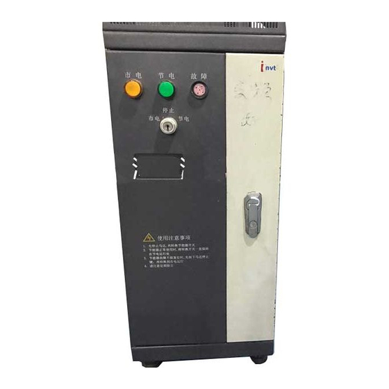
Page 16: Description Of Operation Panel
of a multimeter. Note: Proportional pressure and flow signals must be 0-1A current signals, and the signal acquisition card must be connected in series with such signals. Proportional pressure and flow signals flow into the signal acquisition card from 1IA/2IA, and flow out from 1IB/2IB. If the signal acquisition card is reversely connected, it cannot collect any signals and the injection molding machine has no action signal. - Page 17 Name Function Description Symbol Displays parameters cyclically in the stop display interface and operation display >> SHIFT key SHIFT interface; select the bit to be modified when modifying a parameter Used for operation in keypad operation RUN key mode In operation state, press this key to stop STOP/RESE the operation;...
-
Page 18: Operation Procedures
Symbol Description Frequency unit Current unit Voltage unit Rotation speed unit Percent 3) Digital display area The 5-digit LED display can display various monitoring data such as set frequency and output frequency as well as alarm code. 4.7 Operation Procedures 4.7.1 Parameter setting Three-level menus: 1) Functional code group number (level-1 menu);... - Page 19 Figure 4.7.1 Level-3 Menu Operation Flow Diagram In the level-3 menu, if no bit of parameters flickers, it indicates the functional code cannot be modified. The possible causes include: 1) The functional code cannot be modified, for example, actually measured parameters and operation record parameters.
- Page 20 add or delete functional parameters to or from the shortcut menu when the functional code F7-03 is set to 0. 4.7.2-1 Adding shortcut parameter: To set the functional code P0.00 as a shortcut parameter, for example, operate as follows:...
- Page 21 Stop/Run Figure 4.7.2-1 Example of Adding Shortcut Menu Note: Press <QUICK/JOG> in the level-2 menu of the programming state, the displayed content flickers, prompting whether to save the parameter to the shortcut menu. To confirm the setting, press <DATA/ENT>. The displayed content stops flickering and the operation is completed.
- Page 22 An operation example is as follows: Stop/Run Stop/Run Figure 4.7.2-2 Example of Shortcut Menu Operation Note: In the stop or operation display interface, press <QUICK/JOG> to enter the level-1 shortcut menu. Use the <∧> and <∨> keys to select different shortcut parameters, and then press <DATA/ENT>...
- Page 23 Stop/Run Stop/Run Figure 4.7.2-3 Example of Shortcut Menu Deletion Operation Note: Press <PRG/ESC> in the level-1 shortcut menu, the display flickers, prompting whether to delete the parameter. To confirm the deletion, press <DATA/ENT>. The display stops flickering and shifts to the next shortcut parameter, and the deletion operation is completed.
- Page 24 user does not reset an inverter in the faulty state, the inverter will go to the operation protection state and stop operation. 4.7.4 Parameter copying For details, refer to the functional description of the external LCD keypad. 4.7.5 Motor parameter self-learning The user can select the operation mode with or without PG vector control.
-
Page 25: Installation And Debugging Procedures
obtained from self learning may be incorrect. 4.8 Installation and Debugging Procedures 4.8.1 Connection of lines 4.8.1-1 The connection method of the power line is as follows: Correctly identify the main AC contactor for the startup of the motor, disconnect the 3-phase AC wires between the air switch of the injection molding machine and the main AC contactor (Note that if the main AC contactor has other power lines, re-connect them to the air switch), and then connect the <R, S, T>... - Page 26 4.8.1-3 Upon completion of wiring, test the direction of mains supply mode and energy saving mode, make sure the phase sequence of corresponding motors of the injection molding machine is consistent, and measure signals on two channels with a multimeter to check whether the output is normal. 4.8.2 Perform motor parameter self-learning.
- Page 27 4.8.2-5 After the self-learning, the user cannot change parameters in group P2 at will. If any parameter on the name plate of the motor (P2.01-P2.05) changes, it is necessary to conduct the motor parameter self-learning again. 4.8.2-6 If parameters on the name plate of the motor are unavailable, use default parameters.
- Page 28 is normal; otherwise, motor parameters are incorrect. If the output voltage is excessively high, appropriately reduce the no-load current of the motor (P2.10); if the output voltage is excessively low, appropriately increase the no-load current of the motor (P2.10). 4.8.4 Debugging contents Enter the corresponding functional code and set the parameters by referring to the following settings: 4.8.4-1 Modify the following basic parameters:...
- Page 29 comparative input for two channels. 4.8.4-3 During the use of the energy saver, if protection function is incorrectly enabled, motor parameters may be incorrect. Change P0.00 to 2 (V/F control) and try to identify the cause. 4.8.4-4 Make sure the motor is in the stop state during the switchover between the mains supply mode and energy saving mode;...
-
Page 30: Operating Guide
Operating Guide 5.1 Switchover between Mains Supply Mode and Energy Saving Mode 5.1.1 Energy saving to mains supply operation • The energy saver operates in the energy saving state and the energy saving operation indicator is on. • Shut down the main oil pump motor and make sure the motor stops. •... -
Page 31: Normal Operation Stage Of Energy Saver
technicians must be on the site to inspect product quality. In the energy saving operation state, some injection molding machines may have different technological process flow rate (speed) parameters and pressure parameters from those in the mains supply operation state. Parameters of the injection molding machines in energy saving operation mode are set to values comparatively greater than those set in mains supply operation mode. -
Page 32: Fault Diagnosis
Fault Diagnosis 6.1 Fault Diagnosis and Corrective Action If a fault occurs during the operation of the inverter, the LED display automatically shows the fault. At this time, energy saver has implemented effective protection against the fault. The output terminal stops output and the fault indicator flickers. The fault information is indicated by a code consisting of 2 to 4-digit letters and digits. - Page 33 wheel wires break or fail suddenly. 1. Abnormal input 1. Check power supply; voltage; Acceleration 2. Avoid restarting after operation 2. Restart a rotating stopping. over-voltage motor after transient power failure; 1. Deceleration is too 1. Decrease deceleration time; quick; 2.
- Page 34 operation; Phase loss at input 1. Check power supply; terminals R, S, T Phase loss on the input side 2. Check installation and wiring. 1. U, V, W phase-loss 1. Check output wires; output (or grave imbalance of three 2. Check motor and cables. phases of load) Phase loss on 2.
- Page 35 interruption 1. Poor contact of 1. Check connectors and connectors of the reconnect the wires; control board; 2. Seek for service; 2. Damage to auxiliary power 3. Seek for service; Current detection supply; circuit fault 4. Seek for service. 3. Hall element damaged;...
-
Page 36: Handling Of Common Faults
source source. disappeared 1. Braking line failed 1. Check braking unit or or braking pipe replace braking pipe; damaged; Braking unit fault 2. Increase braking resistors. 2. External braking resistor is low Reserved by the factory 6.2 Handling of Common Faults 6.2.1 Normal protection of energy saver If the energy saver is in the normal protection state, press on the keypad to... -
Page 37: Adjustment Of Common Product Defects
Check whether U, V, W terminals have balanced 3-phase output. If yes, the motor lines or the motor itself may be damaged, or the motor is blocked due to mechanical reasons. Please remove the fault. It may have output but three phases are unbalanced. It may be a fault with the drive board or output module of the energy saver. - Page 38 Defect with material or mold Adjust parameters of the injection temperature molding machine. Product Injection pressure is too low. Increase the value of injection blistering pressure parameters. Injection speed is too high. Decrease the value of injection speed parameters. Defect with material temperature Adjust parameters of the injection or material molding machine.
- Page 39 Defect with material or mold Adjust parameters of the injection Cold slug tempe rature molding machine. rigidity Molding time is too short. Increase value product corresponding time parameters. Material temperature is too high. Adjust related temperature parameters. Injection pressure is too high. Decrease the value of injection pressure parameters.
-
Page 40: Repair And Maintenance
Repair and Maintenance WARNING • Maintenance personnel must follow the stipulated repair and maintenance methods in their work. • Only qualified and service-trained personnel can conduct maintenance operation. • Before carrying out maintenance operation, shut down the power of the inverter first and wait at least 10 minutes. - Page 41 PCB board Dust and dirt Clean dirt dust with compressed air Abnormal noise 1. Clean irrelevant objects vibration, or accumulated 2. Replace the fan operation time exceeding 20,000 hours Electrolytic capacitor Whether color Replace the electrolytic capacitor changes or with foreign smell Heat sink Dust and dirt...
-
Page 42: Warranty
Warranty The product warranty is subject to the following provisions: 8.1 In case of quality defects, the warranty covers: 8.1-1 For domestic use • A warranty of repair, replacement, or return in one month from the date of shipment; • Repair or replacement in three months from the date of shipment;... -
Page 44: Additional Information
Sharper Noise The energy saver adopts frequency conversion technology to drive the oil-pump motor of the injection molding machine. According to characteristics of CHV110 series of energy savers, energy savers are driven by multiple pulses. Therefore, the motor gives out sharp noise of different loudness when it is running at different speeds. -
Page 45: Attachment 1: List Of Functional Parameters
Attachment 1: List of Functional Parameters Functional parameters of the CHV110 energy saver can be functionally divided into sixteen groups (P0 through PF). Where, PF refers to extended functional parameters. After the corresponding extension card is installed on the energy saver, the user can access to the group of parameters. - Page 46 properties of the parameters, so that the user can avoid modifications by mistake). ) “LCD Display” in the seventh column: brief description of the functional parameter name on the LCD display in the operation panel. “Serial No.” in the eighth column: sequence number of the functional code among all the functional codes, and likewise, it also indicates the register address in communications.
- Page 47 Functional Name Detailed Parameter Setting Default Change LCD Display Serial Code Description Range Value P0.00 Speed control 0: Vector control without Speed mode control mode 1: Vector control with PG 2: V/F control P0.01 Run command Keypad command Command channel channel (LED goes off) selection Terminal...
- Page 48 Functional Name Detailed Parameter Setting Default Change LCD Display Serial Code Description Range Value P0.12 Deceleration 3600.0 0.0~3600.0 20.0 s Deceleration time 0 time 0 P0.13 Running 0: Running in default Running direction direction direction selection 1: Running in opposite direction Reverse running...
- Page 49 Functional Name Detailed Parameter Setting Default Change LCD Display Serial Code Description Range Value P4.10 AVR function 0: Invalid selection 1: Full-range enabled selection Disabled upon deceleration P4.11 Energy-saving 0: No action Energy running Automatic saving selection energy-saving running running P5.00 HDI input type 0: HDI1 and HDI2 are...
- Page 50 Functional Name Detailed Parameter Setting Default Change LCD Display Serial Code Description Range Value P5.11 terminal 20: Multi-step pause 0~47 S8 function function selection selection Acceleration/deceleration time selection 1 Acceleration/deceleration time selection 2 23: Simple PLC reset 24: Simple PLC pause 25: PID control pause 26: Wobble frequency pause...
- Page 51 Functional Name Detailed Parameter Setting Default Change LCD Display Serial Code Description Range Value P5.22 Upper AI2 limit 0.00 V 10.00 V 0.00~10.00 10.00 Upper AI2 limit P5.23 Corresponding -100.0%~100.0% -100.0~100.0 100.0% Upper AI2 setting limit setting upper AI2 limit P5.24 AI2 input filter 0.00 s...
- Page 52 Functional Name Detailed Parameter Setting Default Change LCD Display Serial Code Description Range Value P5.40 Corresponding -100.0%~100.0% -100.0~100.0 100.0% Upper HDI1 setting limit setting upper HDI1 frequency limit P5.41 HDI frequency 0.00 s 10.00 s 0.00~10.00 0.10 s HDI1 filter input filter time time P5.42...
- Page 53 Functional Name Detailed Parameter Setting Default Change LCD Display Serial Code Description Range Value P7.14 Type Acceleration ● Fault type 2 previous fault overcurrent (OC1) Deceleration overcurrent (OC2) 6: Constant overcurrent (OC3) Acceleration overvoltage (OV1) Deceleration P7.15 Current fault ● Fault type 3 overvoltage (OV2) type...
- Page 54 Functional Name Detailed Parameter Setting Default Change LCD Display Serial Code Description Range Value P8.17 Action of faulty 0: No action Fault action relay in case 1: Action selection automatic fault reset P8.18 Auto fault 100.0 0.1~100.0 1.0 s Fault reset reset interval interval...
- Page 55 Functional Name Detailed Parameter Setting Default Change LCD Display Serial Code Description Range Value Frequency 101. Pb.08 Frequency 0.00Hz~P0.07 0.00 Hz ~ 0.00 decrease decrease rate (maximum frequency) P0.07 rate upon power failure upon instantaneous power failure Pb.09 Overvoltage 0: protection disabled Overvoltage 102.
-
Page 56: Attachment 2: Standard Wiring Diagram
Attachment 2: Standard Wiring Diagram... - Page 57 (注:18.5KW 以上外接制动单元) (Note: external brake unit in case of over 18.5KW) DCL 直流电机器 DC: DC motor Brake resistor (option) 制动电阻(需外配) Motor 电机 Cooling fan 冷却风扇 三相电源 Three-phase power supply Inverter 变频器 Multifunction input 多功能输入 多功能输入 1 Multifunction input 1 多功能输入 2 Multifunction input 2 多功能输入...
- Page 58 Warranty Card for CHV110 Energy Saver Card No.: Company name Company address Contact Department Title Postal code Model of energy Product saver number Model Code Installation Supplier date Contact Maintainer Through strict quality control and inspected by the quality assurance department, the performance parameters of the product comply with Qualification the standard specified in the Operating Instructions delivered with the...
Need help?
Do you have a question about the CHV110 Series and is the answer not in the manual?
Questions and answers