Table of Contents
Advertisement
Quick Links
Advertisement
Table of Contents

Summary of Contents for H-Tec Education E208
- Page 1 Operating Instructions E208 - 1-Cell Rebuildable PEM Electrolyzer Kit...
-
Page 2: Table Of Contents
Table of Contents Table of Contents Introduction Intended Use General Safety Precautions Contents Required Additional Components/Equipments Optional Equipments Operation of a PEM Electrolyzer Different Operational Modes for Electrolyzers Assembly/Disassembly Operation of the Electrolyzer Cell Technical Data Troubleshooting Disposal www.myhtec.com... -
Page 3: Introduction
Please read through the Operating Instructions carefully before operation. H-TEC Education wishes you many enjoyable hours learning about this tec H-TEC Education wishes you many enjoyable hours learning about this technology with the hnology with the 1-Cell Rebuildable PEM Electrolyzer Kit. -
Page 4: Intended Use
Intended Use The 1-Cell Rebuildable PEM Electrolyzer Kit allows the measurement and demonstration of the principles of Proton Exchange Membrane (PEM) Electrolyzers and PEM Fuel Cells. The system has been developed for teaching and demonstration purposes only. Any other use is prohibited! De-ionized or distilled water, a power supply, and a multimeter are required for the operation of the 1-Cell Rebuildable PEM Electrolyzer Kit. -
Page 5: General Safety Precautions
General Safety Precautions • The system is intended for teaching • The system is not a toy. Operate the and demonstration purposes in schools, 1-Cell Rebuildable PEM Electrolyzer Kit universities, institutions, and companies according to the instructions provided only. in this booklet and keep the cell and the gases produced by the electrochemical •... - Page 6 H-TEC Education does not accept responsibility for injuries or damage sustained in the event of H-TEC Education does not accept responsibility for injuries or damage sustained in the event of these Safety Precautions not being followed.
-
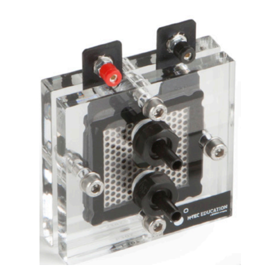
Page 7: Contents
Contents Housing plates Fittings Recessed hex-head Perforated plates screws & washer with electrodes Nuts Catalyst coated membrane Fittings This PEM electrolyzer cell can be fully disassembled and re-assembled in order to see the design aspect and the internal components for educational purposes. This PEM electrolyzer cell can also be used in conjunction with other educational fuel cell kits in order to consume the generated hydrogen and oxygen gases to produce electrical energy. -
Page 8: Operation Of A Pem Electrolyzer
Operation of a PEM Electrolyzer Cell In an electrolyzer cell, the electrical energy that is being provided from an external source is used to split the de-ionized water (or distilled water) in order to generate hydrogen and oxygen gases. In other words, electrical energy is being converted into chemical energy with the aid of the electrolyzer cell. -
Page 9: Different Operational Modes For Electrolyzers
H-TEC Education product such as Storage 80 (Item No: A153) or forcefully-fed (also known as active-fed approach) with the help of a small liquid pump. If the gravity-fed approach is being used, the user should store the water in a manner such that the water level is higher than the top port on the electrolyzer. - Page 10 Different Operational Modes for Electrolyzers “Anode-fed” electrolysis mode “Anode-fed” electrolysis mode Before attaching the power supply to the electrolysis cell, it is advised to follow the following steps: 1. Obtain a pure de-ionized water (or distilled water) in sufficient quantities. 500 mL to 1000 mL of volume of water can be used for multiple hours.
- Page 11 Assembly The 1-Cell Rebuildable PEM Electrolyzer Kit can be completely dismantled. This hardware can be fully disassembled and then reassembled for educational reasons. Note that the catalyst coated membrane (also called CCM) and the electrodes are extremely sensitive components. They can be removed from the cell and shown to students.
- Page 12 Assembly Before refitting the membrane, allow it to soak for at least 5 minutes in deionized water. 1. Place a washer over each of the four bolts. Insert the bolts into one of the housing plates and turn them so the housing plate rests upon the bolt heads (If the black fittings are removed from the housing plate, this operation can be performed on a flat bench top).
- Page 13 5. Place the cathode electrode (catalyzed carbon-based gas diffusion layer) onto the membrane surface. (The catalyzed side of the cathode electrode would be dark black color and the back side of the electrode would have a lighter gray color. The catalyzed side needs to face towards the membrane).
-
Page 14: Operation Of The Electrolyzer Cell
9. Tighten the nuts alternately a little at a time (max. 2.5 turns) until a gap of 4mm is left between the acrylic plates. Caution! Caution! Overtightening may damage the electrodes. We recommend that the distance be checked by a caliper. -
Page 15: Technical Data
Technical Data H x W x D: 100 x 80 x 90 mm Weight: 0.2 kg Output: 35 mL/min Output: 17.5 mL/min Input Voltage Range: 0 - 2 V Input Current Range: 0 - 5 A Electrode Area: 16 cm Guide value for Distilled Water: <2 µS/cm Permitted operating pressure:... - Page 16 © H-Tec Education, 2019. No part of this guide may be reproduced in whole or in part in any manner without the express written permission of H-Tec Education. Subject to technical changes. H-TEC EDUCATION 1902 Pinon Dr. Unit B College Station, TX 77845...
Need help?
Do you have a question about the Education E208 and is the answer not in the manual?
Questions and answers