Table of Contents
Advertisement
Quick Links
Advertisement
Table of Contents

Summary of Contents for Medialon Showmaster Series
- Page 1 Medialon Showmaster Hardware Manual User Reference...
- Page 2 Copyright Information All Rights Reserved. This document is copyrighted © by Medialon Ltd and shall not be reproduced or copied without express written authorization from Medialon Ltd. The information in this document is subject to change without notice. Medialon Ltd assumes no responsibility for errors, and/or omissions contained in this information.
-
Page 3: Table Of Contents
1.2 Objective of this Manual ........................3 2 Showmaster Overview........................4 2.1 Embedded Show Controllers ......................4 2.1.1 Showmaster Architecture ...................... 8 2.1.2 Medialon Showmaster Modes ....................8 2.1.3 Recovery Tool ........................9 2.2 Showmaster Mini Description ......................10 2.2.1 Contents of the Package ...................... 10 2.2.2 Getting Started ........................ - Page 4 3.3.4 Error Messages ........................72 3.3.5 Fatal Messages ........................73 3.4 Showmaster Troubleshootings......................74 3.4.1 Showmaster ......................... 74 3.4.2 Showmaster Editor V2 ......................75 Contact Us ............................76 Medialon Control System p 2 of 80 User Reference Manual M515-2 | 2020-May...
-
Page 5: About This Manual
After reading this manual, you will be able to: • Describe the features of Medialon show control hardware • Set up hardware required for a Show Control installation using Medialon show control hardware Medialon Control System p 3 of 80... -
Page 6: Showmaster Overview
Medialon Manager software such as synchronization and logical programming as well as real time testing. Showmaster LE and Showmaster Pro use a run-time version of Medialon Manager software. A timeline show is created by connecting a computer / laptop to Showmaster via Ethernet, authoring the project, then transferring the finalized file. - Page 7 Medialon is known for. Designed for less demanding applications, it starts with a 20-device limitation, expandable in 10-device batches up to a max of 50 devices. This AV device controller runs Medialon Manager V6 for Showmaster Mini for step-based tasks only.
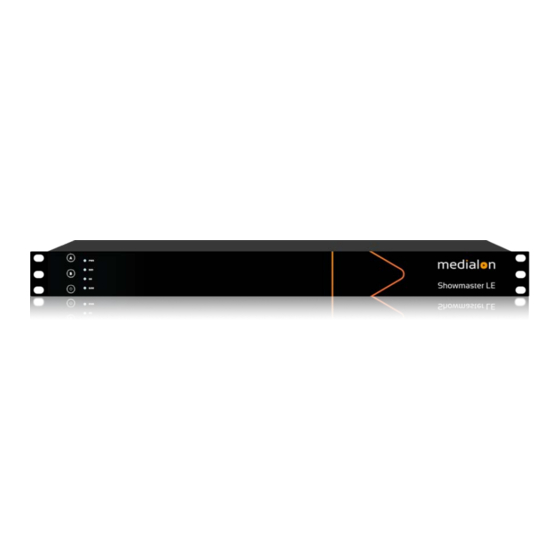
- Page 8 It allows programming of one show at a time, up to 3 Webpanels but does not support 3rd party extension interfaces. Medialon Showmaster LE is a 1 U, full 19” rack-mountable machine; the front panel consists of function buttons and status LEDs.
- Page 9 Showmaster Overview Medialon Showmaster Pro is a 2U, full 19” rack-mountable machine; the front panel consists of an LCD display, function buttons and status LEDs. (Mk 2 illustrated). The rear panel hosts two 10/100/1000 Base-T Ethernet interfaces, digital I/O, serial ports, DMX ports, MIDI ports and timecode input and output ports.
-
Page 10: Showmaster Architecture
Input or Output, two 10/100/1000 Base-T Ethernet ports, and two USB 2.0 type A ports. Showmaster Go runs Windows 10 IoT Enterprise LTSC and includes Medialon Manager (Lite or Pro, depending on licensing) and MAS Pro software (licensed for 16, 32 or 64 channels of Dante output). -
Page 11: Recovery Tool
Showmaster using Medialon Control System Recovery Tool. 2.1.3 Recovery Tool Medialon Showmaster Recovery Tool can be used when a Showmaster LE/Pro is started in Recovery Mode. Your computer can be connected to the Showmaster using a serial communication cable plugged into the Showmaster’s serial port 1. It is also possible to use a network connection to establish the communication. -
Page 12: Showmaster Mini Description
• Medialon Showmaster Mini • Power adaptor 2.2.2 Getting Started Showmaster Mini runs a version of Medialon Manager, and programming can be done directly on the hardware. Medialon Control System p 10 of 80 User Reference Manual M515-2 | 2020-May... -
Page 13: Front Panel Controls
2 × HDMI UHD • 2.2.4 Side Panel The image below shows the side panel of Medialon Showmaster Mini. This has the Phoenix DC power connector and 3.5 mm mini-jack sockets for line out and mic in. 2.2.5 Mounting The rear panel has 3 screw points for attaching a DIN-rail bracket for vertical mounting. - Page 14 Weight 1.2 kg (2.65 lbs) Technical specifications are subject to change without prior notice. Please check www.medialon.com for the latest information. Environmental Specifications Operating Temperature With industrial-grade SSD/mSATA: -30 ~ 70 °C (22 ~ 158 °F), with airflow rate = 0.7 m/sec •...
-
Page 15: Showmaster Le Description
Medialon Showmaster LE • Power adaptor 2.3.2 Getting Started Medialon Showmaster LE is designed as a stand-alone Show Controller. Showmaster LE does not need a keyboard, mouse or screen to work. Medialon Control System p 13 of 80 User Reference Manual... -
Page 16: Front Panel Controls
Press this key to power on Showmaster. Press this key to power off (soft power) Medialon Showmaster. LED Status Messages Four LEDs give a quick overview of the main status of Medialon Showmaster. Medialon Control System p 14 of 80... - Page 17 This LED blinks blue when Showmaster is reading or writing to its internal storage. OS: Showmaster LED This LED indicates the current status of Medialon Showmaster. SHW: Project LED This LED indicates the current status of the Medialon Showmaster Project. Status Default (Not Ready) State Showmaster Starting Up / Shutting Down...
-
Page 18: Rear Panel
Since Showmaster Firmware 2.2.0 Showmaster Storage Fault Pulse IP Address Conflict Detected Pulse ×3 2.3.4 Rear Panel The image below shows the rear panel of Medialon Showmaster LE. • [LAN] RJ45 Ethernet LAN connectors (10/100/1000 Base-T) • [USB]: Not used (*) •... - Page 19 Relay Output Connector Showmaster LE has four relays. Relay outputs are connected to Showmaster LE via 4 terminal block connectors. MIDI Connection Medialon Showmaster LE is provided with MIDI Input and Output port. Connection Cable shield (output only) +5 V DC (source)
-
Page 20: Rack Mount
Adequate clearance for airflow should be provided on both sides so ambient temperature does not exceed the limit. • Please refer to document: M562 Medialon Safety Instructions for installation, use and service. Installation NOTE You need a #2 Phillips screwdriver for rack mount installation. -
Page 21: Technical Specifications
USB Bottom Port: May be used for maintenance purposes (such as image updates/restoration) Serial Interfaces • Number: 2 Connector: 9-pin D-type Male • Format: RS-232 • Digital Interfaces Isolated Inputs: Number: 4 • • Mode: Contact closure Medialon Control System p 19 of 80 User Reference Manual M515-2 | 2020-May... - Page 22 Operating Altitude: sea level to 2000 meters. • Power • External Power Adapter EDACPOWER ELEC • Model EA10683N-120 • AC Input 100-240 V – 2.0 A, 50-60 Hz Medialon Control System p 20 of 80 User Reference Manual M515-2 | 2020-May...
- Page 23 Changes or modifications not expressly approved by the party responsible for compliance could void the user’s authority to operate the equipment FCC responsible: Medialon Ltd 4207 Vineland Rd. Suite M1 Orlando, FL 32811 T: +1 407 505 5200 Medialon Control System p 21 of 80 User Reference Manual M515-2 | 2020-May...
-
Page 24: Showmaster Pro Description
The Medialon Showmaster Pro Package includes: Medialon Showmaster Pro • Power Supply cord • 2.4.2 First Start Medialon Showmaster Pro is designed as a stand-alone Show Controller. Medialon Control System p 22 of 80 User Reference Manual M515-2 | 2020-May... -
Page 25: Front Panel Controls
Hold this key for more than 4 seconds while the Showmaster Pro is powered on to reset it. • Cancel key • Hold this key for more than 4 seconds to power off (soft power) Showmaster Pro. Medialon Control System p 23 of 80 User Reference Manual M515-2 | 2020-May... - Page 26 LCD Display Messages Each time an arrow button is pressed, the next line of information is displayed. 1. [Name] Showmaster’s user-defined Name 2. [Mode] Showmaster’s current mode: Medialon Control System p 24 of 80 User Reference Manual M515-2 | 2020-May...
- Page 27 Starting Up: Showmaster Pro is starting up (from power-on until Showmaster Pro is ready) o Running: Showmaster is running and no Showmaster Editors are connected. Medialon Showmaster also goes to this state when no show file is loaded. o Programming: A Showmaster Editor V2 is connected to Showmaster and a project is...
- Page 28 23. [TC] Timecode port status (Opened/Closed/Failure) LED Status Messages Four LEDs give a quick overview of the main status of Medialon Showmaster. PWR: Power LED This LED lights green when power is present, regardless of whether Showmaster is powered on.
-
Page 29: Rear Panel
Log Trace Error Since Showmaster Firmware 2.2.0 IP address conflict detected Blink 2.4.4 Rear Panel The figure below shows the rear panel of Medialon Showmaster Pro Mk 2. Medialon Control System p 27 of 80 User Reference Manual M515-2 | 2020-May... - Page 30 Digital Input/Output Port Wiring Digital Input Connector Medialon Showmaster Pro has sixteen optically-isolated inputs that can accept either AC or DC signals and are not polarity sensitive. Input signals are rectified by photocoupler diodes and unused power gets dissipated through a 1.8k-ohm resistor in series. The inputs may be driven by either DC or AC sources of 3 to 31 volts (RMS with frequencies of 40 Hz to 10 kHz).
- Page 31 No Connection Relay Output Connector Medialon Showmaster V2 Pro’s relay outputs are comprised of sixteen SPST electromechanical relays. All relays are de-energized at power-on. Relay outputs are connected to Showmaster V2 via a SubD 37 pin Female connector. The wiring may be directly from signal sources or through our optional Breakout Box wiring terminal (SWM_BO_KIT).
- Page 32 / 12 V DC per relay with a maximum of 2 A for the whole 16 relays. MIDI Connection Medialon Showmaster Pro is provided with a MIDI input port and a MIDI output. It uses standard MIDI pinouts. Medialon Control System...
- Page 33 Cable shield (output only) +5 V DC (source) MIDI Data (sink) DMX Connection Medialon Showmaster Pro is provided with 2 DMX 512 ports that can be used for input or output (software configurable in the Resource Setup). Connection Ground Data –...
-
Page 34: Rack Mount
Medialon Showmaster V2 Pro is provided with 8 serial ports. Showmaster Pro is configured with DTE serial ports. Use a crossover (null modem) cable when you want to connect to a computer, for instance to use Medialon Showmaster Recovery Tools. 2.4.5 Rack Mount WARNING –... - Page 35 Rated Load AC: 0.5 A at 125 V AC (62.5 VA max.) • • Rated Load DC: 1 A at 24 V DC (30 W max.) • Max. Switching Voltage: 125 V AC, 60 V DC Medialon Control System p 33 of 80 User Reference Manual M515-2 | 2020-May...
- Page 36 Connector: Isolated BNC female, 75ohms, Input level .65Vpp to 2.0Vpp (1.0Vpp nominal, • ntsc, pal. MIDI Interface Number: 1 MIDI Output / 1 MIDI Input • Connector: MIDI DIN 5 pin - type Female • Medialon Control System p 34 of 80 User Reference Manual M515-2 | 2020-May...
- Page 37 IEC 61000-3-2 and IEC 61000-3-3 • EN 55024 • IEC-61000-4-2 and IEC-61000-4-3 and IEC-61000-4-4 and IEC-61000-4-5 and IEC-61000-4-6 and IEC- 61000-4-11 • IEC/EN/UL 62368-1 • CSA C22.2#62368-1 • IEC 60950-1 Medialon Control System p 35 of 80 User Reference Manual M515-2 | 2020-May...
- Page 38 The SWM_BO_KIT Breakout Kit is a terminal block that can be used to break out Showmaster’s digital I/O DB37 connectors to screw terminals for easy field termination. The Breakout Kit is Medialon Control System p 36 of 80 User Reference Manual...
-
Page 39: Showmaster Go Description
Medialon Showmaster Go • Power adaptor 2.5.2 Getting Started Showmaster Go runs the full Medialon Manager V6 Lite or Pro software, and programming can be done directly on the hardware. 2.5.3 Front Panel Power Button and LEDs Press to power on Showmaster Go. The white ring light on the power button indicates the power state, as does the orange LED to the left of the power button. -
Page 40: Rear Panel
Re-engage the door on the right side, and secure with the screw. 2.5.4 Rear Panel The image below shows the rear panel of Medialon Showmaster Go. Kingston safe lock • 12-19 VDC power inlet with cable inlet clip •... -
Page 41: Mounting
Do not mount with the front panel uppermost. See document M555 Mounting the Medialon Showmaster Go for full details with •... - Page 42 The unit is intended for operation in benign environments; that is, not subject to corrosive or explosive atmospheres, moisture or flammable gases. The unit is non-protected against ingress of liquid (IPx0). The unit is not designed to be subject to excessive mechanical shock or Medialon Control System p 40 of 80 User Reference Manual...
- Page 43 Showmaster Go should not be run without filters, since accumulations of dust inside the unit can affect performance. Cleaning External casing and the front panel should be carefully wiped with a soft cloth and antistatic solution. Medialon Control System p 41 of 80 User Reference Manual M515-2 | 2020-May...
- Page 44 By participating in separate collection of batteries, you will help to ensure proper disposal and to prevent potential negative effects on the environment and human health. Medialon Control System p 42 of 80 User Reference Manual...
- Page 45 Showmaster Overview RoHS compliance Turkey RoHS compliance Türkiye Cumhuriyeti: AEEE Yönetmeliğine Uygundur [Republic of Turkey: In conformity with the WEEE Regulation] China RoHS Hazardous Substance Table Medialon Control System p 43 of 80 User Reference Manual M515-2 | 2020-May...
-
Page 46: Showmaster Maintenance
In this section, you will learn how to maintain your Medialon Showmaster. 3.1 Showmaster Firmware The Medialon Showmaster LE/Pro engine is based on Firmware. This is a package of software components that is installed when Medialon Showmaster is built. Medialon Showmaster’s firmware is based on the same firmware as the Showmaster Editor V2. -
Page 47: Firmware Installation
Showmaster Maintenance 3.1.2 Firmware Installation New versions of Medialon Showmaster firmware must first be installed in Showmaster Editor V2 before Showmaster hardware can be updated. 1. Select Install a Firmware in the File / Firmware management menu of Showmaster Editor V2 2. - Page 48 Click on Add to browse and find the new firmware file (firmwareXXXX.mrtx2) you want to use in Showmaster Editor V2. Delete a firmware If you want to remove from the firmware list an obsolete firmware, click on Delete. Medialon Control System p 46 of 80 User Reference Manual M515-2 | 2020-May...
-
Page 49: Create Custom Firmware
2. The Create Custom Firmware window opens. 3. Select the firmware you want to update. o Use the Browse button [...] to select the firmware file (firmwareXXXX.mrtx2). Medialon Control System p 47 of 80 User Reference Manual M515-2 | 2020-May... - Page 50 Creator Info: enter a comment about this firmware. 5. Select component to add, update or remove Component status is: Genuine: part of firmware released by Medialon. • • Added: new component. •...
- Page 51 Showmaster Maintenance 2. Select the MxM or MRC you want to add or update. Depending how you get this new MxM or MRC, you will select o Medialon Module Installer (*.mis6) o Module Package (*.exe) o Module Package Archive (*.zip) 3.
-
Page 52: Update Showmaster V2 Firmware
3. When firmware creation is completed, Showmaster Editor V2 will ask if you want to install this new firmware. 3.1.4 Update Showmaster V2 Firmware Medialon Showmaster’s firmware updates are executed through the Showmaster Editor V2 interface. Updating Firmware New firmware must be installed in Showmaster Editor V2 before you can proceed to update the firmware in Showmaster. - Page 53 Differences are highlighted with Orange text. 5. Click the Update button to start the Firmware update The Update button is only active when Showmaster Editor V2’s and Showmaster’s firmware are different. Medialon Control System p 51 of 80 User Reference Manual M515-2 | 2020-May...
- Page 54 Showmaster Maintenance 6. Enter your password to confirm the update. Default password is ‘medialon’. The Firmware update password can be changed by the user; Menu Showmaster/Configuration > Passwords. See document M515 Medial Control System Manual for an explanation of the procedure.
-
Page 55: Reset Showmaster Firmware
Showmaster Maintenance Firmware Info If needed or requested by Medialon Support, you can save the list of firmware components. Save: save the content list of both firmware (Editor and Showmaster) in an XML file. • Copy: copies to the clipboard the list of components for both firmware. This list can be •... -
Page 56: Recovery Tools
Showmaster Maintenance 3.2 Recovery Tools Medialon Showmaster’s Installation CD includes tools to maintain Showmaster. When a Showmaster is in Recovery Mode, do not switch off or reset the power using the hard switch or the soft buttons on the front. Doing so could corrupt the core engine. To exit from Recovery Mode, restart or shut down Showmaster from the Recovery Tools application. -
Page 57: Recovery Tool Console
Showmaster using the Medialon Showmaster Recovery Tool console. Medialon Showmaster LE Medialon Showmaster LE switches to recovery mode when the A button is pressed and held during startup. LED for OS and SHW will flash alternately several times. When the OS and Show LEDS start flashing alternately, press the A button a second time to confirm the Recovery Mode. - Page 58 Showmaster Maintenance The Medialon Showmaster Recovery Tool can only be used when Showmaster is started in Recovery Mode. Get Connected Your computer can be connected to Showmaster using a serial (null modem) cable plugged into the Showmaster’s Serial port 1. It is also possible to use a network connection to establish the communication.
- Page 59 2. Medialon Recovery Tool’s response: Connection mode set to ‘tcp’. 3. Type scan 4. Medialon Recovery Tool returns the list of Showmasters 5. Type connect plus the name of the Showmaster and the password (The default password is ‘medialon’) connect Showmaster-ZT1747 medialon 6.
- Page 60 ? Displays information about available commands. help Displays help information about the given command. vers Displays the current version of Medialon Showmaster Recovery Tools. Clear the Recovery console window. exit Quit the Recovery Tools application. mode <‘tcp’|’serial’ [portnumber]>...
- Page 61 Scan for available Showmasters on the network with a delay expressed in milliseconds. Delay is the total time scanning should take place. connect Open communication with the Showmaster connected to the COM port. connect Opens a connection to Showmaster named on the network. The default password is ‘medialon’. Example: [msmrt] > connect Showmaster-B038AE medialon...
- Page 62 [msmrt] > set conf address 192.168.1.79 7. [msmrt] IP Address set to ‘192.168.1.79’ (call ‘commit’ to apply) mask: subnet mask. • Example: set conf mask 255.255.255.0 • gateway: gateway address Medialon Control System p 60 of 80 User Reference Manual M515-2 | 2020-May...
- Page 63 (expressed in days) of log trace history • Example: [msmrt] > set conf loghistsize 10 [msmrt] Log History Size set to ‘10’ (call ‘commit’ to apply) Medialon Control System p 61 of 80 User Reference Manual M515-2 | 2020-May...
- Page 64 Img: Bitmap files added in the project • ResImg: Resources Images built-in • factory Reset the firmware to factory default. See also Showmaster Firmware. To confirm the operation, use the ‘commit’ command. Medialon Control System p 62 of 80 User Reference Manual M515-2 | 2020-May...
-
Page 65: Test Mode Commands
[msmrt] > test on [msmrt] Test set to On. The front panel display indicates Test Mode status The following commands are only available when Medialon Showmaster is in Test Mode. Serial Resources open serial Opens serial port. Example: [msmrt] >... - Page 66 N 1” set rts <portnumber> <"on"|"off"|"hchk"> Sets RTS of serial port <portnumber> “hchk” turns on hardware handshaking for RTS/CTS Example: [msmrt] > 3 hchk set dtr <portnumber> <"on"|"off"|"hchk"> Medialon Control System p 64 of 80 User Reference Manual M515-2 | 2020-May...
- Page 67 ‘!XX’ notation for hexadecimal bytes <data> [msmrt] > write serial Hello!0D Digital I/O Resource open digital Opens the Digital I/O resource Example: [msmrt] > open digital [msmrt] Digital Resource opened. Medialon Control System p 65 of 80 User Reference Manual M515-2 | 2020-May...
- Page 68 The ‘get digital’ command and ‘Events’ report digital input activity in the Showmaster Recovery Tools console window. DMX512 Resources open dmx <portnumber> Opens DMX port <portnumber> Example: [msmrt] > open dmx 1 [msmrt] DMX Port 1 opened. close dmx <portnumber> Medialon Control System p 66 of 80 User Reference Manual M515-2 | 2020-May...
- Page 69 Closes the MIDI ports. Example: [msmrt] > close midi [msmrt] MIDI Port closed. event midi <"on"|"off"> Turns on or off event reporting for the MIDI In port. Medialon Control System p 67 of 80 User Reference Manual M515-2 | 2020-May...
- Page 70 [msmrt] > open timecode [msmrt] Timecode Port opened. close timecode Closes the Timecode Input resource. Example: [msmrt] > close timecode [msmrt] Timecode Port closed. event timecode <"on"|"off"> Medialon Control System p 68 of 80 User Reference Manual M515-2 | 2020-May...
-
Page 71: Showmaster Logs
Timecode ‘Events’ report changing timecode values once per second (so the Showmaster Recovery Tools console window does not scroll too quickly). 3.3 Showmaster Logs Medialon Showmaster traces its main activity into logs. Showmaster Editor V2 provides a way for you to read these logs. 1. Connect Showmaster Editor to a Showmaster. -
Page 72: Manage Logs Windows
Normal: This type of message is for all events that executed normally in the running processes of Showmaster. • Info: This type of message is a highlighted normal event. Medialon Control System p 70 of 80 User Reference Manual M515-2 | 2020-May... -
Page 73: Notify Messages
Error: An error occurred which has significant impact. Something is no longer working. • Fatal: The same as Error, but it makes the system stop working. • Debug: Low Level traces, should be activated after a request by Medialon support. Select the sources of messages: • mShowmasterCore: Showmaster’s main engine •... -
Page 74: Alarm Messages
• System information cannot be collected. < Unable to start TCP Server > • The TCP server for Showmaster Editor V2 and Medialon Manager connections cannot be started. < Unable to start Pipe Server > • The server that manages the dialog with ManagerRT cannot be started. -
Page 75: Fatal Messages
< ManagerRT Stopped due to zero division error > A zero division error occurred in the project; runtime has stopped. ManagerRT Messages ManagerRT Task Kernels Timed Out. • ManagerRT Task Condition Kernel Timed Out. • Medialon Control System p 73 of 80 User Reference Manual M515-2 | 2020-May... -
Page 76: Showmaster Troubleshootings
Showmaster Maintenance 3.4 Showmaster Troubleshootings This section helps resolve problems you may encounter while using Medialon Showmaster V2. 3.4.1 Showmaster Common Problems and Solutions: Problem Check These Items Does not turn on Check that the power cable is plugged in. -
Page 77: Showmaster Editor V2
Check recovery mode. Forget Connection Password Contact Medialon Support. Firmware upgrader generation failed Check USB stick Disk full or locked. For further information, contact your Medialon dealer. Medialon Control System p 75 of 80 User Reference Manual M515-2 | 2020-May... -
Page 78: Contact Us
Contact Us Contact Us Find more on our website www.medialon.com and on social media or contact our support team at support@medialon.com Medialon Control System p 76 of 80 User Reference Manual M515-2 | 2020-May... - Page 80 E: support@medialon.com W: medialon.com Medialon Ltd, UK Medialon Ltd, US (registered address) 2 The Courtyard 4207 Vineland Rd. Shoreham Road Suite M1 Upper Beeding Orlando West Sussex FL 32811 BN44 3TN T: +44 (0) 1903 81229 T: +1 407 505 5200...
Need help?
Do you have a question about the Showmaster Series and is the answer not in the manual?
Questions and answers