Table of Contents
Advertisement
Advertisement
Table of Contents

Subscribe to Our Youtube Channel
Related Manuals for AR SMOOTH FLITE 16 RRS

Summary of Contents for AR SMOOTH FLITE 16 RRS
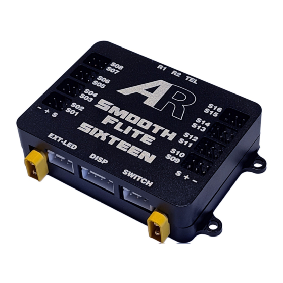
- Page 1 Smooth Flite 16 Version User Guide...
-
Page 2: Table Of Contents
Table Of Contents Introduction --------------------------------------------------------------------------------------------------------------------- 4 Important Points --------------------------------------------------------------------------------------------------------------- 4 Features -------------------------------------------------------------------------------------------------------------------------- 5 Installation and Mounting Instructions ---------------------------------------------------------------------------------- 6 Mounting the Smart Display ------------------------------------------------------------------------------------------------ 7 General Usage and Screen Information ---------------------------------------------------------------------------------- 8 Main Menu ---------------------------------------------------------------------------------------------------------------------- 9 Input to Output Routing ---------------------------------------------------------------------------------------------------- 10 Channel Monitor Screen --------------------------------------------------------------------------------------------------- 11 Sub Trim and End Point Menu -------------------------------------------------------------------------------------------- 11 15 Point Servo Matching -------------------------------------------------------------------------------------------------- 12... - Page 3 Table Of Contents continued. Smooth Flite Advanced Stabilisation Features (Auto Gain Control AGC) -------------------------------------- 36 (Variable Gain Control VGC) Proportional Mode & Aerobatic Mode ------------------------------------------- 37 Smooth Flite Advanced Stabilisation Features ( Variable Gain Control VGC) --------------------------------- 37 Smooth Flite Detailed Functions—Channel Assignment ------------------------------------------------------- 38,39 Smooth Flite Detailed Functions—Aileron ------------------------------------------------------------------------ 40,41 Smooth Flite Detailed Functions—Elevator ---------------------------------------------------------------------- 42,43 Smooth Flite Detailed Functions—Rudder ------------------------------------------------------------------------ 44,45...
-
Page 4: Introduction
Thank you for your purchase of the Advance Radio Smooth Flite System. The Advanced Radio Smooth Flite system was designed with Giant Scale Models in mind and combines Power Distribution, Flite Stabilisation and a 16 Channel Servo control system in the lightest package in it’s class (less than 50 grams). In the past trimming and matching servos would take place via the transmitter. -
Page 5: Features
Included Items: 1 x Live feedback touch screen Smart display 1 x Smooth Flite power distribution module. 1 x Power LED 3 x Receiver cables Optional Items: Pin Flag switch with Advance Radio Flag Remote FOB Switch with Advance Radio Flag Magnetic Switch with Advance Radio Flag 2 x Receivers Features:... -
Page 6: Installation And Mounting Instructions
Installation and Mounting Instructions In this section we will explain how to mount both the Smooth Flite and the Smart Display. The Advanced Radio Smart System gives you the choice of mounting the Smart Screen in the Model or leaving it disconnected for normal flying. The Smooth Flite will operate in normal flying mode without the Smart Screen Connected. -
Page 7: Mounting The Smart Display
Mounting the Smart Display To save weight the Smart Screen is not required for normal flying usage. It is only required for programming the Smooth Flite. Should you wish to mount the Smart Screen in the model for quick battery checks etc then we recommend 2 options of mounting the Smart Screen display. -
Page 8: General Usage And Screen Information
General Usage and Screen Information Important: The Smart Screen Display supplied with the Smooth Flite is a touch screen display. It is used in both setup and provides feedback to the user about battery voltage and milliamps used. The screen can be mounted in a model for quick and easy use. However the Smooth Flite will operate during normal flying mode without the Smart Screen connected. -
Page 9: Main Menu
Main Menu Return Returns back to the previous screen. Power Press here to go to the battery setup and reset menu. Monitor Press here to go to servo programming menu. I/O Routing Pressing here will take you to the channel routing screen. -
Page 10: Input To Output Routing
I/O Routing Screen Save Takes you back to the previous screen and saves your routing choices. - and + buttons Changes the input Channel from 1 to 16 Note: you can only assign servos to channels that are available from your Receiver. Example: you can not assign a servo to channel 16 when using a 10 channel radio S01 to S16... -
Page 11: Channel Monitor Screen
Channel Monitor screen Return Takes you back to the previous screen. Changes the page to higher channels. Channel Bars The bars show the current input channels and position. Note: The bars have two colours. Blue = no servo output has been assigned. Green = one or more servo outputs has been assigned to this channel. -
Page 12: 15 Point Servo Matching
15 Point Servo Matching Return Takes you back to the previous screen. Reset Resets the sub trim values back to default. Vertical Bars Shows the sub trim applied to the servo. The sub trim values can be changed using the DEC, buttons. -
Page 13: First Time Battery Setup
Smooth Flite. You will also need to en- sure the Smart display is plugged into the switch as it is used for programming. Upon power up, you will see the AR logo. After a few seconds the Smart Screen will be shown. - Page 14 Step 4 This is the battery setup screen. Using the arrows (DEC, INC) next to Bat Capacity mA cycle through until you see the correct capacity that matches your battery packs. Note: Step 4 is extremely important! Please en- sure the capacity is set correctly to the battery packs you are using.
-
Page 15: Protocol Selection Arxl Version
Protocol Selection Before connecting receivers to the Smooth Flite RRS you will need to select the appropriate protocol to match to your transmitter system. Smooth Flite system supports the following protocols: SBUS, SBUS2, XBUS, Jeti EX Bus, FRSKY, HOTT, SRXL, SRXL2 and Core in SBUS mode. -
Page 16: Installing The Receivers Arxl Version
Installing the Receivers ARXL Version The Smooth Flite ARXL includes two receiver connection cables and possible a third telemetry cable. (For Spektrum SRXL2 receivers you will need to purchase part number BRC857), Standard receiver cables are generally supplied preconnected to the Smooth Flite. -
Page 17: System Specific Receiver Installation
Please use 3 x SPM4651T receivers for full range teleme- try. The SPM4651T use a new 4 pin connector. You will require adaptor leads SKU BRC857 from AR for the SPM4651T receivers to connect to SF16. -
Page 18: Installing Satellites Spektrum Version
System Specific Receiver installation Graupner HOTT System. Smooth Flite supports all receivers with HOTT protocol. HOTT receivers provide up to 16 channels (depending and transmitter) into the Smooth Flite routed to any of the 16 servo output channels. Connect receivers to Smooth Flite ports R1 and R2 to the SUMD port of the HOTT receiver. -
Page 19: Input Channel To Servo Output Routing
Input Channel to Servo Output Routing During this stage, we will install the receiver and servos. Important: Check the recommended voltage range of your servos, supplying excessive voltage to your servos may cause damage to the servos. Before connecting any servos to the Smooth Flite we recommend reading through the following steps. - Page 20 Note: The monitor gives you a visual indication of the assigned input channels from your receiver. Your new Smooth Flite RRS comes with primary control surfaces pre-assigned to simplify your setup. Hint: Create a new model on your transmitter with dual aileron channels, single elevator and single rudder channels.
-
Page 21: Servo Sub-Trim: Reversing Method 1
Servo Sub-Trim: Reversing Method 1 The Smooth Flite system is designed to allow you to easily trim up to 16 servo outputs for precise servo matching in multi ganged servo installations, Elevators, flaps and multi motor installations. If servos require matching we recommend for simplicity you do this in the Smooth Flite system. -
Page 22: Servo Sub-Trim, Reversing Method
Servo Sub-Trim: Reversing Method 2 We also provided an input channel MONITOR screen so you can easily visualise which transmitter channel is assigned to which servo output and then easily trim and match. The following example assumes Channel 1 from your transmitter has been assigned to S01 on the Smooth Flite as per factory setup. -
Page 23: 15 Point Matching
15 Point Matching (Smooth Flite All Versions) 15 point matching is useful for getting the best possible match between servos. This includes mechanically matched servos (aileron) or non mechanically matched (left and right elevator, flaps or multi engine models). We are now going to go through the 15 point servo matching process. -
Page 24: Receiver Menu
Receiver Menu All Smooth Flite RRS systems have the added feature of monitoring the connection between the Re- ceiver and the transmitter. This can be used to assist in the optimal placement of your receivers dur- ing setup. We will now go through a process of how to check the quality of the connection between your receiver and your transmitter. -
Page 25: Setting Fail Safe
Setting Fail Safe Smooth Flite 16 has Fail Safe function which should be used for all receiver types. Note: It is extremely important that FAILSAFE is set before flying. We recommend at least setting FAILSAFE on throttle to either idle or off as a matter of safety. Note: It is important to make sure that FAILSAFE is OFF or not set in the radio. -
Page 26: Telemetry With Spektrum Tm1000
Telemetry with SBUS2 Receivers Smooth Flite RRS comes with the added ability of downlink telemetry when using a 7008SB or 7003SB SBUS/ SBUS2 receiver. Note: In order to receive telemetry via Smooth Flite, you must plug the receiver signal into the SBUS2 port. Please ensure that the primary receiver (first bound receiver in a dual receiver setup) is plugged into the R1 port on the Smooth Flite. -
Page 27: Factory Reset
Factory Reset When you use the Sub-Trim and other functions these functions are saved to the permanent memory of the Smooth Flite. RRS. There may be situations where you will want to initialise your Smooth Flite back to the original factory settings. Switching the Smooth Flite to a different model for example would be one of the situations. -
Page 28: Additional Screens
Additional Screens Cockpit Simulation Screens The Smooth Flite also comes with additional Simulation screens that simulate a real cockpit. These include an artificial horizon and instrumentation. To view these new screens touch the bottom center of the Smart Screen page. Cockpit Simulation Screens You can cycle through the cockpit screens by tapping the area at the bottom of the... - Page 29 Smooth Flite Gyro Menus Smooth Flite is much more than just a simple Gyro system. It provides an intelligent system that calcu- lates parameters from 4 different sensors to predict the nature of the model to provide, well, the smoothest flying characteristic available today. Smooth Flite combines a 3 axis Gyro, Accelerometer, Compass and Barometer, to provide for more advanced understanding of a model’s flight characteristics.
-
Page 30: Smooth Flite Gyro Menus
Smooth Flite Gyro Menus Advanced Controls The Advanced Controls menu is the gateway to many of the Smooth Flite advanced features. We will discuss these more in detail later. Parameter Editing To edit a parameter or value you tap the value to be edited. -
Page 31: Smooth Flite Gyro Setup Wizard
Smooth Flite Gyro Setup Wizard As we mentioned earlier we have included a setup Wizard to guide you through the Smooth Flite assisted flight setup process. Using just the Wizard and pre-Flight check information on the following pages is all that is required to get a standard dual Aileron, Elevator and Rudder model ready to fly with Smooth Flite. - Page 32 Smooth Flite Setup Wizard You will be presented with the Smooth Flite Easy Setup page. Please take the time to read this page and when ready press “NEXT”. You can also leave the setup Wizard at any time by tapping the “NO”...
- Page 33 Smooth Flite Setup Wizard After tapping “NEXT” from the Model Weight Page you will see the Master Channel Assignment instruction page. Smooth Flite uses a MASTER control channel on your transmitter to turn SMOOTH FLITE On/Off and to select low and high speed gain settings. You need to assign a 3 stage switch on the transmitter for this function along with a transmitter output channel.
- Page 34 Smooth Flite Setup Wizard After tapping “NEXT” from the Trim page you will see the control surface assignment page. Here you select which controls (Ailerons, Elevators, Rudder) to apply Smooth Flite control. We suggest for the first flight you apply Smooth Flite to Rudder only so you can get a feel for flying with Smooth Flite.
-
Page 35: Smooth Flite Gyro Pre Flight Checks
Smooth Flite Gyro Pre-Flight Checks If you have completed the Smooth Flite Wizard then at this point you have setup for a standard dual ailer- on, Elevator and Rudder model. Before flying the model YOU MUST check the control surfaces are reacting correctly to direction changes. -
Page 36: Smooth Flite Advanced Stabilisation Features
Smooth Flite Gyro Pre-Flight Checks Master Switch Check If the Pre-flight checks on the previous page check out then you are ready to fly with Smooth Flite acti- vated. Remember from the Wizard setup you assigned a Master Switch control to a 3 stage switch on the transmitter. -
Page 37: (Variable Gain Control Vgc) Proportional Mode & Aerobatic Mode
Advanced Stabilisation Features Variable Gain Control (VGC) In addition to setting high speed and low speed gain settings on the Master Switch, Smooth Flite offers an optional additional Variable Gain channel which can be assigned to say, a rotary dial , a switch or an advanced mix on the transmitter. -
Page 38: Smooth Flite Detailed Functions-Channel Assignment
Smooth Flite Detailed Functions: Channel Assignment OK, so we have gone through the Smooth Flite setup Wizard and we will now discuss each of the parameters of the Smooth Flite gyro in detail. Channel Assignment Page Tapping the “Chan Assign” button from the Smooth Flite menu will take you to the “CHANNEL ASSIGN” page (shown right). - Page 39 Smooth Flite Detailed Functions: Channel Assignment Variable Gain Control (VGC) In addition to setting high speed and low speed gain settings on the Master Switch, Smooth Flite offers an optional additional Variable Gain channel which can be assigned to say, a rotary dial , a switch or an advanced mix on the transmitter.
-
Page 40: Smooth Flite Detailed Functions-Aileron
Smooth Flite Detailed Functions: Aileron Aileron Channel Page Tapping the “Aileron” button on the Smooth Flite Menu will take you to the “Aileron Channel” page. SF Active (on Ailerons) Checking SF Active from the Aileron Channel page (as shown in the picture to the right) will activate Smooth Flite on Ailerons. - Page 41 Smooth Flite Detailed Functions: Ailerons Aileron Hi and Low Gain This is the level of Smooth Flite gain applied to the aileron by the Master Gain Switch. High Gain is used for low speed flying and landing approaches. Low Gain is used for normal flying conditions.
-
Page 42: Smooth Flite Detailed Functions-Elevator
Smooth Flite Detailed Functions: Elevator Elevator Channel Page Tapping the “Elevator” button from the Smooth Flite menu will take you to the “Elevator Channel” page. SF Active (on Elevator) Checking SF Active from the Elevator Channel page (as shown in the picture to the right) will activate Smooth Flite on Elevator. - Page 43 Smooth Flite Detailed Functions: Elevator Elevator Hi and Low Gain This is the level of Smooth Flite gain applied to the Elevator by the Master Gain Switch. High Gain is used for low speed flying and landing approaches. Low Gain is used for normal flying conditions.
-
Page 44: Smooth Flite Detailed Functions-Rudder
Smooth Flite Detailed Functions: Rudder Rudder Channel Page Tapping the “Rudder” button from the Smooth Flite menu will take you to the “Rudder Channel” page. SF Active (on Rudder) Checking SF Active from the Rudder Channel page (as shown in the picture to the right) will activate Smooth Flite on Rudder. - Page 45 Smooth Flite Detailed Functions: Rudder Rudder Hi and Low Gain This is the level of Smooth Flite gain applied to the Rudder by the Master Gain Switch. High Gain is used for low speed flying and landing approaches. Low Gain is used for normal flying conditions.
-
Page 46: Smooth Flite Trim
Smooth Flite Trim Smooth Flite uses maximum, minimum and centre stick positions in many of its calculations. If you have completed the wizard then you would have already captured these values. However you can redo these values if for example control limits have changed in the transmitter. -
Page 47: Smooth Flite Advanced Mixing Functions-Crow And Flaperons, Aileron Differential
Smooth Flite Advanced Mixing Functions Crow and Flaperons Crow and Flaperons (as the names suggests) operates on ailerons by providing offset from the normal aileron position. Smooth Flite provides Offset 3 positions which operate from a 3 position switch. You can of course operate this function from a 2 position switch or a slider or mixed from a channel say, flaps. -
Page 48: Elevon Mixing
Elevator Direction will reverse the direction of the elevator portion in the elevons. This can be used in combination with the Servo Out Sub Trim pages to get correct directional movement in any setup. Check the AR product page for setup videos. -
Page 49: V-Tail Mixing
Elevator Direction will reverse the direction of the elevator portion in the elevons. This can be used in combination with the Servo Out Sub Trim pages to get correct directional movement in any setup. Check the AR product page for setup videos. -
Page 50: Gyro Assisted Steer Trim, Dual Rudder Speed Brakes
Smooth Flite Advanced Mixing Functions Gyro Assisted Steering Sub Trim This smooth Flite mix feature allows you to assign gyro assisted rudder to a separate Servo output and then sub trim the servo output from the transmitter. Activate Steer Trim—turns the mix ON/OFF Control Channel—... -
Page 51: Vectored Thrust Switching
Smooth Flite Advanced Mixing Functions Vectored Thrust Switching Many modern Sports Jets and some Scale Jets come with single and twin Vectored thrust. For the first time Vectored Thrust pilot this can be a daunting experience so we have provided a mechanism where Gyro assisted vectored Thrust can be switched to ON/OFF remotely from the transmitter. -
Page 52: Setup Hints-Gyro Controlled Rudder And Ground Steering
Smooth Flite Setup Hints Gyro controlled Rudder and Ground steering One of the excellent features of Smooth Flite RRS is having unlimited Input to Output routing capabilities as well as sophisticated trimming capabilities. For the best Smooth Flite assisted outcome the following should be performed using Smooth Flite trim functions. -
Page 53: Setup Hints-Setting Up Flaps With A Single Tx Channel
Smooth Flite Setup Hints Setting up Flaps with a single TX channel In this Hint we will talk about how to apply a single input channel to control flaps. We will use conventions of a brief Explanation and [The steps to get to the pages to achieve the outcome] Method. -
Page 54: Setup Hints-Elevons, Thrust Vectoring And Canards Setup
Smooth Flite Setup Hints Elevons, Thrust Vectoring and Canards setup One of the excellent features of Smooth Flite RRS is having unlimited Input to Output routing capabilities as well as sophisticated trimming capabilities. For the best Smooth Flite assisted outcome the following should be performed using Smooth Flite trim functions. - Page 55 Smooth Flite Setup Hints Elevons, Thrust Vectoring and Canards setup CONTINUED If the ailerons are moving the wrong way go to the Smooth Flite sub trim page for the ailerons and reverse their movement. [Main Menu Monitor tap the input channel indicator assigned to the Aileron Tap the “Assigned To Smart Bus Output”...
-
Page 56: Frequently Asked Questions
General FAQ Can I mount the Smart Display in my model. The Smart Display can be mounted as a simulation cockpit for RC aircraft, however, it should be shock mounted to protect against vibration. All Advanced Radio ARXL products (Smooth Flite and Smart Bus) provide downlink telemetry so in most cases it is not necessary to mount the display in the model. -
Page 57: Smooth Flite Specifications
Operating Voltage: 5.0 — 12.0v (Receivers must be capable of these voltages) Battery type: 2s LiPo/Lion, 2s LiFePo4, 5s NiMH/NiCd Receiver: Dual AR Active Redundancy technology Receiver Voltage: Supported protocols: Jeti EXBUS, SBus, SBus2, JR/DFA XBus-A, HOTT, SRXL, SRXL2. Telemetry:... -
Page 58: Channel Routing Sheet
Channel Routing for Model _______________________ Smooth Flite Transmitter Function Function Transmitter Smooth Flite Servo Output Servo Output Input Input... - Page 59 Notes...
- Page 60 Smooth Flite 5 Year Replacement Warranty At Advanced Radio our products are designed and tested to very high standards. We use only the highest quality electronic components sourced from reputable manufacturers; ST Micro, BOSCH, TDK, Linear Technology, Texas Instruments, Cypress Semiconductor Corp and NPX. Our circuit boards are assembled in Australia in a certified ISO900-2008 and ISO 13485 medical devices risk management quality assurance environment.
-
Page 61: Usage Statement
Smooth Flite servo outputs are filtered to remove spurious noise. This allows the usage of long servo lead lengths. We strongly advise the usage of high quality servo leads like the AR ProLine capable of carrying currents experienced with today’s high power high voltage servos.
Need help?
Do you have a question about the SMOOTH FLITE 16 RRS and is the answer not in the manual?
Questions and answers