
Summary of Contents for WEISS LS 280
- Page 1 Operating manual Linear Assembly System LS 280 Mechanical system documentation 980-240511001 / EN 05 / 2011...
- Page 2 All rights in this document are the copyright of WEISSGmbH. This document may not be copied or reproduced, in whole or in part, without the written permission of WEISS GmbH. This document is only intended for the user of the product described and may not be passed on to third parties, in particular competitors.
-
Page 3: Table Of Contents
10.3. Dismantling and disposal ................47 11. Service and spare parts ..................49 11.1. Ordering spare parts ................... 49 11.2. Spare parts ....................49 12. Appendix ......................50 12.1. Personal notes .................... 50 Linear Assembly System LS 280 Mechanical System Documentation R05-2011 3/52... - Page 4 Central lubrication unit with mounting plate ..............36 Piston distributor with lubricating lines, pressure switch and vent screw ...... 36 Replacing the toothed belt ..................... 45 Replacing the workpiece carrier train ................46 4/52 Linear Assembly System LS 280 Mechanical System Documentation R05-2011...
-
Page 5: Introduction
Definition Linear Assembly Systen LS 280 The Linear Assembly System LS 280 is designed as a base machine for installation in a total machine that is used for assembly and test tasks in the area of automation enginee- ring. It is designed exclusively for indexed horizontal linear motion of a payload that cannot react in a manner that is hazardous to personnel, material, or the environment when manipulated. -
Page 6: Laws / Ec Directives / Norms
In addition to this operating manual, further documents are required to ensure safe ope- ration of this machine. The specifications stated in these documents are to be observed. • Operating Manual LS 280 electrical system documentation • System-dependant documentation LS 280 6/52 Linear Assembly System LS 280 Mechanical System Documentation R05-2011... -
Page 7: Operating Manual
A sign with the signal word NOTICE indicates potenti- al material damage or provides additional information which should be observed when operating the machi- Linear Assembly System LS 280 Mechanical System Documentation R05-2011 7/52... -
Page 8: Guarantee
The figures used are examples. There may be differences between the illustrations and the actual delivery. Guarantee The machine is covered by a guarantee of 24 months without shift limitations. 8/52 Linear Assembly System LS 280 Mechanical System Documentation R05-2011... -
Page 9: Safety
• national accident prevention guidelines and company-internal guidelines are complied with. • VDE regulations are complied with. • the EMC legislation is complied with during installation. Linear Assembly System LS 280 Mechanical System Documentation R05-2011 9/52... -
Page 10: Safety Equipment For The Machine
The operator must take all measures to protect his personnel against injury by the machine. These include: • Protective grid with monitored safety door • Emergency stop circuit • Light barriers or switch mats • Warning indicators 10/52 Linear Assembly System LS 280 Mechanical System Documentation R05-2011... -
Page 11: Residual Hazards
Loose clothing, long hair, or hanging jewelry can be caught, pulled along, or wound in by the moving parts. Do not wear loose cloting, long, air or suspended jewelry when handling the machine. Failure to comply with this prohibitory instruction result in severe injuries. Linear Assembly System LS 280 Mechanical System Documentation R05-2011 11/52... - Page 12 A failure or malfunction of the control system can lead to injuries caused by uncon- trolled system behaviour or automatic startup. The operator must take all measures to ensure that the machine is only operated in compliance with regulations. 12/52 Linear Assembly System LS 280 Mechanical System Documentation R05-2011...
-
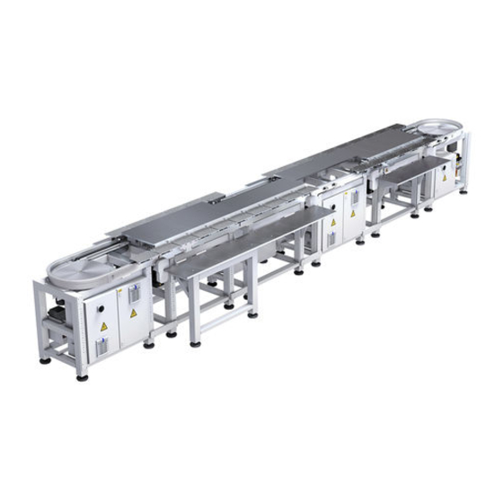
Page 13: Product Description
Control packages as well as electrical components of the machine are described in operating manual LS 280 electrical system documentation. Fig. 1: Modules of the machine See order layout in the system-dependant documentation LS 280. Linear Assembly System LS 280 Mechanical System Documentation R05-2011 13/52... -
Page 14: Function Of The Modules
Cam drive with gear transmission, belt drive and three-phase current motor [2] • Steel guide rail with hardened and ground profile guide track • Sensors X = direction of transport Fig. 3: Single locking station Fig. 4: Double locking station 14/52 Linear Assembly System LS 280 Mechanical System Documentation R05-2011... -
Page 15: Stationary Support
[3] move on stationary attached support rollers [4] into the respective position. The sup- ports are adjusted for the specific system (see order layout in the system-dependant documentation LS 280 for the max. permissible application of force and transfer of force). Fig. 5:... -
Page 16: Workpiece Carrier In Locked Position
The positioning and orientation of the transport cam relative to the drive shaft [1] is realised by an alignment pin. The transport cam is connected to the drive shaft via a clamping set. Fig. 8: Drive unit of the locking station 16/52 Linear Assembly System LS 280 Mechanical System Documentation R05-2011... -
Page 17: Sensors At The Intake Of The Locking Station
"Pre-trigger" (front) "Pre-trigger" (front) Fig. 11: Sensors on the drive unit at Fig. 12: Sensors on the drive unit at indexing pitch 70, 140, 280 mm indexing pitch 560 mm Linear Assembly System LS 280 Mechanical System Documentation R05-2011 17/52... -
Page 18: Assembly Cell With Stop Station As Manual Workstation
Depending on the requirement you can stop each workpiece carrier individually or stop the entire workpiece carrier train via the stop unit. Fig. 14: Stop unit 18/52 Linear Assembly System LS 280 Mechanical System Documentation R05-2011... -
Page 19: Sensors On The Intake Of The Stop Station
Opening the stop unit releases the workpiece carrier. The release can be executed via an internal signal, e.g. from a foot switch, or it can also be executed externally via the customer's control. Linear Assembly System LS 280 Mechanical System Documentation R05-2011 19/52... -
Page 20: Belt Section With Workpiece Carrier Train
1800 mm and 2400 mm can only be used as outgoing belt and intermediate belt) Fig. 17: Belt section with workpiece carrier Fig. 18: Belt drive with motor (without cover) train 20/52 Linear Assembly System LS 280 Mechanical System Documentation R05-2011... -
Page 21: Corner Unit 180
Cast aluminium base body • Drive housing with gear transmission, belt drive and three-phase current motor • Catch plate of anodised aluminium 448,5 Fig. 19: Corner unit 180° Fig. 20: Corner unit 90° Linear Assembly System LS 280 Mechanical System Documentation R05-2011 21/52... -
Page 22: Workpiece Carrier Train
Lateral roller [5] • Plastic slide block [7], constant contact force • Steel switch strip [3], chemically nickel-plated • Rubber buffer [4] • Connecting rod [6] Fig. 21: Workpiece carrier train 22/52 Linear Assembly System LS 280 Mechanical System Documentation R05-2011... - Page 23 (Product and device) At a indexing pitch of 140 mm 2 products are on the carrier plate At a indexing pitch of 70 mm 4 products are on the carrier plate Linear Assembly System LS 280 Mechanical System Documentation R05-2011 23/52...
-
Page 24: Lubricating Point In The Guide Rail
This central lubrication unit is activated automatically and is pulse-cycled by the WEISS control, so that a icating is always present. -
Page 25: Technical Data
The A-weighted emission sound pressure level do not exeed the allowable peak. 3.3.3 Type plate The mechanical modules of the machine are identified with a WEISS type plate; where the serial number of the respective module is specified. The type plate shown is only intended as an example of a module and is not identical to the actual type plate on the product described. - Page 26 Belt section (dimension 1800 mm) Appr. 74 kg Belt section (dimension 2400 mm) Appr. 96 kg Corner unit Appr. 50 kg Workpiece carrier train with carrier plates Appr. 6 kg 26/52 Linear Assembly System LS 280 Mechanical System Documentation R05-2011...
-
Page 27: Transportation
Appliances and auxiliary equipment approved for transportation 4.2.1 Machine transportation For transport WEISS GmbH dismantles and packs the pre-assembled and tested machine in units that are suitable for transport. The transport vehicles are unloaded, and transport to the set-up location can be execu- ted by forklifts or the load can be attached to ropes and straps through an indoor crane. -
Page 28: Transportation Damage
Details of the scope of delivery are provi- ded in the order characteristics. Damage detected should be immediately reported to and confirmed by the transportation company. 28/52 Linear Assembly System LS 280 Mechanical System Documentation R05-2011... -
Page 29: Intermediate Storage
Open damage during with filter (free of dirt and dust) inspection No aggressive vapours and no Check that anticor- vibrations rosion protection is Protected against insect unspoiled damage Linear Assembly System LS 280 Mechanical System Documentation R05-2011 29/52... -
Page 30: Installation
Improperly placed or improperly fastened system parts can fall or tip over. • Ensure that all components are installed in accordance with the described arrange- ment. • Ensure that specified tightening torques are maintained. 30/52 Linear Assembly System LS 280 Mechanical System Documentation R05-2011... -
Page 31: Installation Prerequisites
If delivered with base frame or base plate particularly ensure that • The supporting floor is level and rigid. Maximum permissible evenness deviation over the entire placement surface: 0.1 mm. Linear Assembly System LS 280 Mechanical System Documentation R05-2011 31/52... -
Page 32: Installing The Machine
The pre-assembled modules are set up according to the layout of the machine and the markings on the modules. The mechanical modules of the machine are identified with a WEISS type plate; where the serial number of the respective module is specified. -
Page 33: Limit Switch Strip Mounted In Correct Position
Unscrew the four screws [1] of the marked catch disc [2]. • Take off the catch disc. • Remove the plug [3]. • Replace the catch disc and screw it down. Fig. 30: Removing the plug Linear Assembly System LS 280 Mechanical System Documentation R05-2011 33/52... -
Page 34: Inserting Workpiece Carrier Trains
7. Screw in the fixing screws [4] and firmly tighten. 8. Check the transitions on the guide profile to ensure that they are even. Fig. 31: Inserting workpiece carrier trains 34/52 Linear Assembly System LS 280 Mechanical System Documentation R05-2011... -
Page 35: Mounting The Carrier Plate
[2]. Vertical acting process forces have to be passed in directly above the support rollers. Fig. 33: Stationary support Linear Assembly System LS 280 Mechanical System Documentation R05-2011 35/52... -
Page 36: Instructions On Disposal Of Packaging Material
Fig. 35: Piston distributor with lubricating mounting plate lines, pressure switch and vent screw Instructions on disposal of packaging material Packaging materials should be reused or disposed of correctly in compliance with natio- nal regulations. 36/52 Linear Assembly System LS 280 Mechanical System Documentation R05-2011... -
Page 37: Commissioning
The following should be checked during commissioning • the drive motors for faultless operation. • no excessive noise development is detected. A strong development of noise can indicate improper assembly. Linear Assembly System LS 280 Mechanical System Documentation R05-2011 37/52... -
Page 38: Initial Commissioning
6.2 Initial commissioning Initial commissioning The machine must be commissioned according to the specifications in the supp- lied operating manual LS 280 electrical system documentation. The specifications provided in this document must be followed when commissioning the machine. Recommissioning Risk of injury emanating from an operationally unsafe machine. -
Page 39: Operation
The operating personnel workstations are determined by the owner of the system or pro- duct in which the machine is integrated. Safe operation and control are the responsibility of the operator. Linear Assembly System LS 280 Mechanical System Documentation R05-2011 39/52... -
Page 40: Malfunctions
Customer Service Please provide the following details if you require the assistance of our Customer Service: • Serial number according to WEISS type plate at the approbriate module • Description of the malfunction that has occurred • Time and attendant circumstances of the malfunction that has occurred •... -
Page 41: Maintenance
Ensure that all work steps for maintenance are performed in the specified sequence. • Ensure that specified tightening torques are maintained. • Ensure that all foreign objects are removed from the work area after the maintenance. Linear Assembly System LS 280 Mechanical System Documentation R05-2011 41/52... -
Page 42: Maintenance Work
We recommend that you manually trigger several lubricating pulses on the control after cleaning and starting up the system. 42/52 Linear Assembly System LS 280 Mechanical System Documentation R05-2011... -
Page 43: Maintenance
Utilised oil: Shell Omala 680 (CLP 680 conforming to DIN 51517) Oil quantity (litres): 0.67 Drive corner unit 0.095 Drive locking station Linear Assembly System LS 280 Mechanical System Documentation R05-2011 43/52... -
Page 44: Repair
4. Remove old toothed belt. 5. Pull on new toothed belt. 6. Tighten the four fixing screws for the motor flange. 7. Cover plate of the toothed belt box 8. Perform a trial run. 44/52 Linear Assembly System LS 280 Mechanical System Documentation R05-2011... -
Page 45: Replacing The Toothed Belt
8. Tension the toothed belt by sliding the belt deflection element with a screwdriver [8] and firmly tightening the fixing screws [1] on the belt deflection element. Fig. 36: Replacing the toothed belt Linear Assembly System LS 280 Mechanical System Documentation R05-2011 45/52... -
Page 46: Replacing The Workpiece Carrier Train
Replacing electrical components Information on replacing electrical machine components is provided in the supplied electrical system documentation. The information in this documentation must be complied with when replacing electrical components. 46/52 Linear Assembly System LS 280 Mechanical System Documentation R05-2011... -
Page 47: Decommissioning / Dismantling / Disposal
• Note that emerging lubricant, solvent, preserving agents, etc. can cause cauterizing and burns if they come into direct contact with skin. Linear Assembly System LS 280 Mechanical System Documentation R05-2011 47/52... - Page 48 Cast aluminium (housing, workpiece carriers) • Aluminium (profiles) • Copper (motors and electric cables) • Plastic (electrical lines, toothed transport belt, electrical components) • Electronic components (sensors and control, frequency inverter) • Lithium (battery) 48/52 Linear Assembly System LS 280 Mechanical System Documentation R05-2011...
-
Page 49: Service And Spare Parts
Please supply us with the following details when ordering spare parts: • Serial number according to the WEISS type plate on the appropriate module • WEISS article number and designation of the spare part according to the spare parts list • Number of spare parts required... -
Page 50: Appendix
Appendix 12.1 Personal notes --------------------------------------------------------------------------------------------------------------------- --------------------------------------------------------------------------------------------------------------------- --------------------------------------------------------------------------------------------------------------------- --------------------------------------------------------------------------------------------------------------------- --------------------------------------------------------------------------------------------------------------------- --------------------------------------------------------------------------------------------------------------------- --------------------------------------------------------------------------------------------------------------------- --------------------------------------------------------------------------------------------------------------------- --------------------------------------------------------------------------------------------------------------------- --------------------------------------------------------------------------------------------------------------------- --------------------------------------------------------------------------------------------------------------------- --------------------------------------------------------------------------------------------------------------------- --------------------------------------------------------------------------------------------------------------------- --------------------------------------------------------------------------------------------------------------------- --------------------------------------------------------------------------------------------------------------------- --------------------------------------------------------------------------------------------------------------------- --------------------------------------------------------------------------------------------------------------------- --------------------------------------------------------------------------------------------------------------------- --------------------------------------------------------------------------------------------------------------------- --------------------------------------------------------------------------------------------------------------------- --------------------------------------------------------------------------------------------------------------------- --------------------------------------------------------------------------------------------------------------------- --------------------------------------------------------------------------------------------------------------------- --------------------------------------------------------------------------------------------------------------------- --------------------------------------------------------------------------------------------------------------------- --------------------------------------------------------------------------------------------------------------------- 50/52 Linear Assembly System LS 280 Mechanical System Documentation R05-2011... - Page 51 12.1 Personal notes --------------------------------------------------------------------------------------------------------------------- --------------------------------------------------------------------------------------------------------------------- --------------------------------------------------------------------------------------------------------------------- --------------------------------------------------------------------------------------------------------------------- --------------------------------------------------------------------------------------------------------------------- --------------------------------------------------------------------------------------------------------------------- --------------------------------------------------------------------------------------------------------------------- --------------------------------------------------------------------------------------------------------------------- --------------------------------------------------------------------------------------------------------------------- --------------------------------------------------------------------------------------------------------------------- --------------------------------------------------------------------------------------------------------------------- --------------------------------------------------------------------------------------------------------------------- --------------------------------------------------------------------------------------------------------------------- --------------------------------------------------------------------------------------------------------------------- --------------------------------------------------------------------------------------------------------------------- --------------------------------------------------------------------------------------------------------------------- --------------------------------------------------------------------------------------------------------------------- --------------------------------------------------------------------------------------------------------------------- --------------------------------------------------------------------------------------------------------------------- --------------------------------------------------------------------------------------------------------------------- --------------------------------------------------------------------------------------------------------------------- --------------------------------------------------------------------------------------------------------------------- --------------------------------------------------------------------------------------------------------------------- --------------------------------------------------------------------------------------------------------------------- --------------------------------------------------------------------------------------------------------------------- --------------------------------------------------------------------------------------------------------------------- --------------------------------------------------------------------------------------------------------------------- --------------------------------------------------------------------------------------------------------------------- Linear Assembly System LS 280 Mechanical System Documentation R05-2011 51/52...
- Page 52 Weiss GmbH Sondermaschinentechnik | Siemensstraße 17 | D-74722 Buchen Telefon +49(0)6281-5208-0 | Fax +49(0)6281-520899 | info@weiss-gmbh.de | www.weiss-gmbh.de...
Need help?
Do you have a question about the LS 280 and is the answer not in the manual?
Questions and answers