Sign In
Upload
Download
Table of Contents
Contents
Add to my manuals
Delete from my manuals
Share
URL of this page:
HTML Link:
Bookmark this page
Add
Manual will be automatically added to "My Manuals"
Print this page
×
Bookmark added
×
Added to my manuals
Manuals
Brands
IFM Manuals
Laser Level
LK122 Series
Operating instructions manual
IFM LK122 Series Operating Instructions Manual
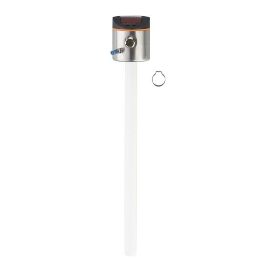
Electronic level sensor
Hide thumbs
1
Table Of Contents
2
3
4
5
6
7
8
9
10
11
12
13
14
15
16
17
18
19
20
21
22
23
24
25
26
27
28
29
30
31
page
of
31
Go
/
31
Contents
Table of Contents
Bookmarks
Table of Contents
Table of Contents
Preliminary Note
1�1 Symbols Used
Safety Instructions
Items Supplied
Functions and Features
4�1 Applications
4�2 Restriction of the Application Area
Getting Started
5�1 Example Configuration
Function
6�1 Measuring Principle
6�2 Operating Principle / Features of the Unit
6�2�1 Notes on the Integrated Overflow Prevention
6�2�2 Display and Switching Functions
6�2�3 Offset for Indicating the Real Level in the Tank
6�2�4 Defined State in Case of a Fault
6�2�5 IO-Link Function
6�3 Password Protection against Inadvertent Manipulation
Installation
7�1 Other Installation Notes
7�1�1 Marking of the Installation Height
Electrical Connection
Operating and Display Elements
Menu
10�1 Menu Structure
10�2 Password Protection
Parameter Setting
11�1 Parameter Setting in General
11�2 Basic Settings
11�2�1 Set Unit of Measurement [Uni]
11�2�2 Set Offset [OFS]
11�2�3 Set Medium [Medi]
11�2�4 Set Overflow Prevention
11�2�5 Adjust the Overflow Prevention [Cop]
11�3 Setting the Output Signals for OUT1
11�3�1 Setting the Output Function [Ou1]
11�3�2 Define Switching Limits [SP1] / [Rp1] (Hysteresis Function)
11�3�3 Define Switching Limits [FH1] / [FL1] (Window Function)
11�3�4 Set Switch-On Delay [Ds1]
11�3�5 Set Switch-Off Delay [Dr1]
11�3�6 Define Switching Logic [P
11�3�7 Set Response of the Output in Case of a Fault [FOU1]
11�3�8 Configure Display [Dis]
11�3�9 Reset All Parameters to Factory Setting [Res]
11�4 Changing the Password [Code]
11�5 Enter Password [Key
Operation
12�1 Operation Indication
12�2 Read the Set Parameters
12�3 Error Indications
12�4 Output Response in Different Operating States
Technical Data
13�1 Setting Values [OFS]
13�2 Setting Values
13�3 Calculation Aids
13�3�1 Definition "From the Cover
13�3�2 Definition "From the Bottom
13�4 Setting Ranges [SP1] / [FH1] and [Rp1] / [FL1]
Maintenance/Cleaning/Change of Medium
Factory Setting
Advertisement
Quick Links
Download this manual
Operating instructions
Electronic level sensor
UK
LK122x
Table of
Contents
Previous
Page
Next
Page
1
2
3
4
5
Advertisement
Table of Contents
Need help?
Do you have a question about the LK122 Series and is the answer not in the manual?
Ask a question
Questions and answers
Related Manuals for IFM LK122 Series
Laser Level IFM LK1222 Operating Instructions Manual
Electronic level sensor (31 pages)
Laser Level IFM LK1223 Operating Instructions Manual
Electronic level sensor (31 pages)
Laser Level IFM LK1224 Operating Instructions Manual
Electronic level sensor (31 pages)
This manual is also suitable for:
Lk1222
Lk1223
Lk1224
Table of Contents
Print
Rename the bookmark
Delete bookmark?
Delete from my manuals?
Login
Sign In
OR
Sign in with Facebook
Sign in with Google
Upload manual
Upload from disk
Upload from URL


Need help?
Do you have a question about the LK122 Series and is the answer not in the manual?
Questions and answers