Table of Contents
Advertisement
Head Office
Sonardyne International Limited
Blackbushe Business Park
Yateley, Hampshire
GU46 6GD United Kingdom
Lodestar Hardware
Manual
UM-8084-101
Lodestar
Hardware Manual
T. +44 (0) 1252 872288
F. +44 (0) 1252 876100
E.
support@sonardyne.com
www.sonardyne.com
Document Ref: UM-8084-101
Issue: A– Rev 8
© Sonardyne International Limited 2013
1
Advertisement
Table of Contents

Summary of Contents for Sonardyne Lodestar
- Page 1 Document Ref: UM-8084-101 Lodestar Hardware Issue: A– Rev 8 Manual © Sonardyne International Limited 2013 UM-8084-101 Lodestar Hardware Manual Head Office Sonardyne International Limited T. +44 (0) 1252 872288 Blackbushe Business Park F. +44 (0) 1252 876100 Yateley, Hampshire support@sonardyne.com GU46 6GD United Kingdom www.sonardyne.com...
-
Page 2: Document History
All rights reserved. No part of this document shall be reproduced, stored in a retrieval system or transmitted by any means, electronic, mechanical, photocopying, recording, or otherwise, or translated into any language without the written permission of Sonardyne International Limited. -
Page 3: Table Of Contents
Purpose ............................6 How this manual is arranged ...................... 6 About Lodestar ..........................8 Introduction ..........................8 Front panel features of the Surface Lodestar................9 Connectors of the Subsea Lodestar ..................12 Operation ..........................14 Warranty ........................... 15 Technical Specifications ....................... 17 Introduction .......................... -
Page 4: Figures
Figure 24 – Subsea Lodestar Comms C1 Cable – CPN 820-0068............52 Figure 25 – Subsea Lodestar Comms C1 Test Cable – CPN 820-0070 ..........53 Figure 26 – Subsea Lodestar Comms Ethernet Tail Cable – CPN 820-0071 ........54 Figure 27 –... -
Page 5: Tables
Document Ref: UM-8084-101 Lodestar Hardware Issue: A– Rev 8 Manual © Sonardyne International Limited 2013 Tables Table 2 – Battery and charge status LEDs .................... 11 Table 3 – Transceiver and data LEDs ....................12 Table 5 – Lodestar Versions ......................... 17... -
Page 6: S. Department Of Commerce License
US Department of Commerce Re-Export Licence under which the product was sold. If any servicing or repair of the Lodestar, or Lodestar portion of the product is required consult your nearest Sonardyne office for the best current advice. - Page 7 Lodestar. manual Anyone who uses the Lodestar should make sure they read the relevant parts of this manual. If the computer that holds this electronic manual is connected to a printer, any part of it can be printed.
-
Page 8: About Lodestar
Lodestar Attitude and Heading Reference System (AHRS) / Inertial Navigation System (INS). The Lodestar is a solid-state AHRS/INS that includes three Ring Laser Gyroscopes (RLGs) and three linear accelerometers. These inertial-grade components provide raw data to the Sonardyne-developed gyrocompass algorithm, which uses them to produce a full range of accurate real-time motion and attitude measurements in all sea states. -
Page 9: Front Panel Features Of The Surface Lodestar
Front panel features of the Surface Lodestar Sonardyne has designed the Lodestar AHRS to be as simple as possible to install, connect, configure, and operate. To support this design principle, the front panel of... - Page 10 Ethernet A 100BaseT Ethernet port. When using Lodestar to supply NMEA outputs to multiple listening devices, use a two-wire shielded twisted pair. See section 5.7 beginning on page 31 for information. The RS485 differential line consists of two pins – ‘A’ and ‘B’ as defined in the NMEA standard: ‘A’...
- Page 11 The ON/OFF power switch is a push button switch. Press and release to start the switch Lodestar. Press and hold for at least 4 seconds to close down the Lodestar. CAUTION The ON/OFF power switch controls all power to operate the Lodestar Attitude and Heading Reference System, including power from the backup battery.
-
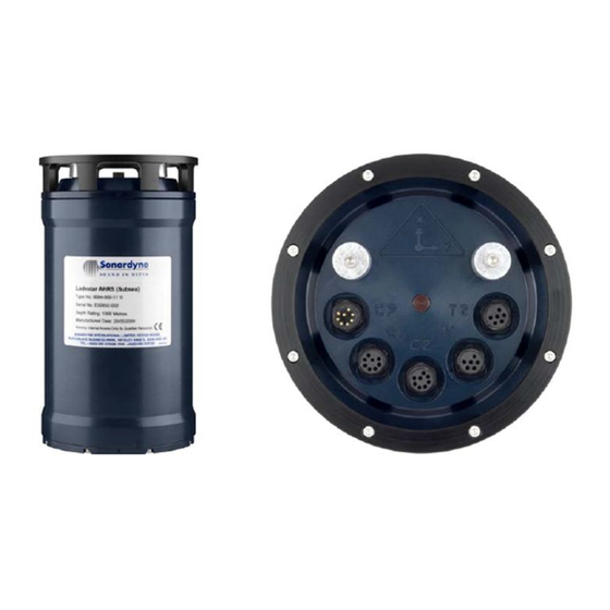
Page 12: Connectors Of The Subsea Lodestar
16 AWG cable (or better) should be used for this. Connectors of the Subsea Lodestar The subsea version of the Lodestar AHRS does not include any operator controls or indicators. The unit’s housing is cylindrical with two end-caps to provide watertight seals of the appropriate depth rating. - Page 13 The connectors are open-faced without their dummy plugs fitted and are not waterproof in this state. NEVER deploy the Subsea Lodestar in water unless all connectors on the end-cap have their correct plugs or dummy plugs fitted properly.
-
Page 14: Operation
See section 7.1 starting on page 36 for instruction on how to upgrade the Lodestar firmware. In addition to the ON/OFF switch for the Surface Lodestar described in section 3.2 Shutdown the Lodestar can be turned off via the terminal interface. -
Page 15: Warranty
Issue: A– Rev 8 Manual © Sonardyne International Limited 2013 At this point, the Lodestar can be shutdown by typing in the shutdown command SYS SHUTDOWN 1 three times, as shown in the example below. The Lodestar will then shutdown. - Page 16 Any changes will be notified to the holder of this document at the discretion of Sonardyne. For a list of contact details for Sonardyne’s offices and agents, please refer to Product section 8.2 “Sonardyne Offices and Agents” beginning on page 41.
-
Page 17: Technical Specifications
Introduction Sonardyne International Limited exercises a policy of continual product development and improvement. The technical specifications included in this chapter are subject to change without notice. If necessary, contact Sonardyne International Limited for details of the current specification. Product Table 5 lists the versions of the Lodestar currently available. -
Page 18: Physical
Document Ref: UM-8084-101 Lodestar Hardware Issue: A– Rev 8 Manual © Sonardyne International Limited 2013 Physical The physical specification of the Surface Lodestar are shown in Figure 3 and Surface Figure 4. version Figure 3 – Physical specifications – Surface Lodestar... -
Page 19: Figure 4 - Physical Specifications - Surface Lodestar (Continued)
Document Ref: UM-8084-101 Lodestar Hardware Issue: A– Rev 8 Manual © Sonardyne International Limited 2013 Figure 4 – Physical specifications – Surface Lodestar (continued) -
Page 20: Figure 5 - Physical Specifications - 1000 M Subsea Lodestar
Lodestar Hardware Issue: A– Rev 8 Manual © Sonardyne International Limited 2013 Subsea The physical specifications of the Subsea Lodestars are shown in Figure 5, Figure 6 and Figure 7. versions Figure 5 – Physical specifications – 1000 m Subsea Lodestar... -
Page 21: Figure 6 - Physical Specifications - 3000 M Subsea Lodestar
Document Ref: UM-8084-101 Lodestar Hardware Issue: A– Rev 8 Manual © Sonardyne International Limited 2013 Figure 6 – Physical specifications – 3000 m Subsea Lodestar... -
Page 22: Figure 7 - Physical Specifications - 5000 M Subsea Lodestar
Document Ref: UM-8084-101 Lodestar Hardware Issue: A– Rev 8 Manual © Sonardyne International Limited 2013 Figure 7 – Physical specifications – 5000 m Subsea Lodestar... -
Page 23: Electrical
© Sonardyne International Limited 2013 Electrical Electrical power requirement 110 / 240 VAC 50 / 60 Hz (for use with the surface version of Lodestar only), or 24 or 48 VDC (for use with the surface or the subsea versions of... - Page 24 Heave Range ±99 metres Accuracy (real time) The greater of 5 cm or 5% of measured heave Bandwidth User selectable Resolution 0.01 metres Note: The power demand listed above is correct for the Lodestar when used as a standalone instrument.
-
Page 25: Installation
CAUTION shipping container until it is ready to be installed in the prepared location. Inspect the Lodestar and all the supplied parts on receipt, and check the shipment Inspection includes all the items listed on the shipping documents. Inform Sonardyne immediately if there are any parts missing, or if any of the supplied parts show signs of damage. -
Page 26: Installation Location
© Sonardyne International Limited 2013 Installation location The Lodestar can be installed at any convenient location on the vessel, from where it will deliver accurate measurements. However, to gain optimal performance from the system, identify a location to install the Lodestar that conforms as closely as possible to the following criteria: •... -
Page 27: Site Preparation
The site preparations you make before you install the Lodestar are important. The alignment of the Lodestar to the vehicle is discussed in section 5.5 and in depth in the Lodestar AHRS Operation Manual UM 8084-107. Figure 8 and Figure 9 show the mounting arrangement for the surface and the subsea version of the Lodestar. -
Page 28: Figure 8 - Mounting Arrangement - Surface Lodestar
Document Ref: UM-8084-101 Lodestar Hardware Issue: A– Rev 8 Manual © Sonardyne International Limited 2013 Figure 8 – Mounting arrangement – Surface Lodestar Figure 9 – Mounting arrangements – Subsea Lodestar... -
Page 29: Alignment
Manual © Sonardyne International Limited 2013 Alignment Course When you install the Lodestar you should attempt to align to within ±2° of the vehicle’s axes, see Figure 30 on page 58 for an explanation of the Lodestar alignment reference frame. -
Page 30: Nmea Connections To Listening Equipment
© Sonardyne International Limited 2013 NMEA Connections to Listening Equipment It is possible to connect a single Lodestar to more than one listening unit so that, with Lodestar transmitting multiple NMEA sentences, each listener selects the sentences they require and ignores all others. -
Page 31: Troubleshooting
If technical support from Sonardyne is required, provide information about the Lodestar configuration in use at the time when the problem occurred. You can do this by supplying a copy of the relevant configuration file saved automatically by the Lodestar, see Lodestar AHRS Operation Manual UM-8084-107 for instructions. -
Page 32: Figure 11 - Lodestar Test Procedure
Document Ref: UM-8084-101 Lodestar Hardware Issue: A– Rev 8 Manual © Sonardyne International Limited 2013 Figure 11 – Lodestar test procedure... -
Page 33: Check List
Make a note of the answers to each bullet point, referring to the relevant sub-section for more details. The following bullet points all relate to general information about Lodestar. Information needed Refer to the detailed explanations for each bullet point in the list. -
Page 34: Recovery Procedures
Lodestar into an RS232 mode. Apply power to the Lodestar and wait 2 minutes for it to start up. Open the Lodestar PC Utility and attempt to Connect to Lodestar. - Page 35 Press the Reset to Default button. Press Yes to confirm that you want to reset Lodestar to default. The PC Utility will reboot Lodestar and reset it to factory default state. It will then wait for Lodestar to re-boot. After the boot process has completed the PC Utility will attempt to connect to Lodestar using factory default settings.
-
Page 36: Maintenance
If using a test cable then check that the blue connectors are joined to put Lodestar into an Lodestar RS232 mode. If not using an NSH then power to the Lodestar and wait 2 minutes for it to start up. - Page 37 Document Ref: UM-8084-101 Lodestar Hardware Issue: A– Rev 8 Manual © Sonardyne International Limited 2013 Start the Press the Download Firmware button… Firmware Upgrade Confirm that you wish to upgrade firmware by pressing Yes… The following dialog box will be displayed.
- Page 38 Manual © Sonardyne International Limited 2013 When a file is selected a warning will be displayed asking if the file is definitely a Lodestar firmware file. Press YES to continue. Next select a baud rate for the download. Sonardyne recommends 115200 baud for all firmware downloads.
- Page 39 Once the download is complete press the Done button. At this point the utility will re-boot the Lodestar. Once complete the PC Utility will re-program Lodestar to give it the same configuration that it had before the upgrade began. Therefore it should now be ready for use.
-
Page 40: Technical Support
08:30 to 17:30 UK time. Outside these hours, the call is automatically transferred to a local agency that will log the details of your emergency and alert the appropriate Sonardyne personnel. Sonardyne’s aim is to make sure that emergency requests are dealt with immediately during office hours and are responded to within 30 minutes at all other times. -
Page 41: Sonardyne Offices And Agents
Issue: A– Rev 8 Manual © Sonardyne International Limited 2013 Sonardyne Offices and Agents Sonardyne offices are shown as blue bullets in Figure 14. Figure 14 – Sonardyne Office Locations 8.2.1 Sonardyne Office locations Sonardyne International Limited has offices in the following locations: 8.2.1.1... - Page 42 Document Ref: UM-8084-101 Lodestar Hardware Issue: A– Rev 8 Manual © Sonardyne International Limited 2013 8.2.1.4 Singapore Sonardyne Asia Pte. Ltd. 34 Loyang Crescent Block B Singapore 508993 Tel: +65 6542 1911 Fax: +65 6542 6937 e-mail: asia.sales@sonardyne.com 8.2.1.5 Brasil (Rio das Ostras) Sonardyne Brasil Ltda Av.
-
Page 43: Appendix A - Cable Drawings
Document Ref: UM-8084-101 Lodestar Hardware Issue: A– Rev 8 Manual © Sonardyne International Limited 2013 Appendix A – Cable Drawings Figure 15 – Lodestar Surface Console Cable Tail – CPN 820-0054... -
Page 44: Figure 16 - Lodestar Surface Console Test Cable - Cpn 820-0057
Document Ref: UM-8084-101 Lodestar Hardware Issue: A– Rev 8 Manual © Sonardyne International Limited 2013 Figure 16 – Lodestar Surface Console Test Cable – CPN 820-0057... -
Page 45: Figure 17 - Lodestar Surface Comms Test Cable - Cpn 820-0061
Document Ref: UM-8084-101 Lodestar Hardware Issue: A– Rev 8 Manual © Sonardyne International Limited 2013 Figure 17 – Lodestar Surface Comms Test Cable – CPN 820-0061... -
Page 46: Figure 18 - Lodestar Surface Transceiver Cable Tail - Cpn 820-0062
Document Ref: UM-8084-101 Lodestar Hardware Issue: A– Rev 8 Manual © Sonardyne International Limited 2013 Figure 18 – Lodestar Surface Transceiver Cable Tail – CPN 820-0062... -
Page 47: Figure 19 - Lodestar Surface Transceiver Test Cable - Cpn 820-0064
Document Ref: UM-8084-101 Lodestar Hardware Issue: A– Rev 8 Manual © Sonardyne International Limited 2013 Figure 19 – Lodestar Surface Transceiver Test Cable – CPN 820-0064... -
Page 48: Figure 20 - Auxiliary Lemo Cable Assembly - Cpn 820-6817
Document Ref: UM-8084-101 Lodestar Hardware Issue: A– Rev 8 Manual © Sonardyne International Limited 2013 Figure 20 – Auxiliary Lemo Cable Assembly – CPN 820-6817... -
Page 49: Figure 21 - Gyro Power Cable - Cpn 820-6828
Document Ref: UM-8084-101 Lodestar Hardware Issue: A– Rev 8 Manual © Sonardyne International Limited 2013 Figure 21 – Gyro Power Cable – CPN 820-6828... -
Page 50: Figure 22 - Lodestar Subsea Console Cable - Cpn 820-0065
Document Ref: UM-8084-101 Lodestar Hardware Issue: A– Rev 8 Manual © Sonardyne International Limited 2013 Figure 22 – Lodestar Subsea Console Cable – CPN 820-0065... -
Page 51: Figure 23 - Lodestar Subsea Console Test Cable - Cpn 820-0067
Document Ref: UM-8084-101 Lodestar Hardware Issue: A– Rev 8 Manual © Sonardyne International Limited 2013 Figure 23 – Lodestar Subsea Console Test Cable – CPN 820-0067... -
Page 52: Figure 24 - Subsea Lodestar Comms C1 Cable - Cpn 820-0068
Document Ref: UM-8084-101 Lodestar Hardware Issue: A– Rev 8 Manual © Sonardyne International Limited 2013 Figure 24 – Subsea Lodestar Comms C1 Cable – CPN 820-0068... -
Page 53: Figure 25 - Subsea Lodestar Comms C1 Test Cable - Cpn 820-0070
Document Ref: UM-8084-101 Lodestar Hardware Issue: A– Rev 8 Manual © Sonardyne International Limited 2013 Figure 25 – Subsea Lodestar Comms C1 Test Cable – CPN 820-0070... -
Page 54: Figure 26 - Subsea Lodestar Comms Ethernet Tail Cable - Cpn 820-0071
Document Ref: UM-8084-101 Lodestar Hardware Issue: A– Rev 8 Manual © Sonardyne International Limited 2013 Figure 26 – Subsea Lodestar Comms Ethernet Tail Cable – CPN 820-0071... -
Page 55: Figure 27 - Subsea Lodestar Comms Ethernet Cable - Cpn 820-0072
Document Ref: UM-8084-101 Lodestar Hardware Issue: A– Rev 8 Manual © Sonardyne International Limited 2013 Figure 27 – Subsea Lodestar Comms Ethernet Cable – CPN 820-0072... -
Page 56: Figure 28 - Subsea Lodestar Transceiver Cable Tail - Cpn 820-0073
Document Ref: UM-8084-101 Lodestar Hardware Issue: A– Rev 8 Manual © Sonardyne International Limited 2013 Figure 28 – Subsea Lodestar Transceiver Cable Tail – CPN 820-0073... -
Page 57: Figure 29 - Subsea Lodestar Transceiver Test Cable - Cpn 820-0078
Document Ref: UM-8084-101 Lodestar Hardware Issue: A– Rev 8 Manual © Sonardyne International Limited 2013 Figure 29 – Subsea Lodestar Transceiver Test Cable – CPN 820-0078... -
Page 58: Appendix B - Lodestar Reference Frame
Document Ref: UM-8084-101 Lodestar Hardware Issue: A– Rev 8 Manual © Sonardyne International Limited 2013 Appendix B – Lodestar Reference Frame Figure 30 – Lodestar Reference Frame...
Need help?
Do you have a question about the Lodestar and is the answer not in the manual?
Questions and answers