Table of Contents
Advertisement
Quick Links
Advertisement
Table of Contents

Summary of Contents for VibrAlign Fixturlaser Go
- Page 1 Get Going! ©2010 Vibralign, Inc. T R A I N I N G M A N U A L...
-
Page 2: Table Of Contents
T A B L E C O N T E N T S Introduction to Alignment ..........................1 Chapter 1 Prealignment Considerations ........................3 Chapter 2 Using the GO ...............................6 Chapter 3 Assisted Practice ............................14 Chapter 4 Student Practice-Aligning to 1800 rpm Tolerances ..................15 Chapter 5 Student Practice-Aligning to 3600 rpm Tolerances .................. -
Page 4: Introduction To Alignment
I N T R O D U C T I O N A L I G N M E N T ALIGNMENT BASICS The machines we align: Basic The most basic machines to align consist of a driver and driven element. The driven unit is usually considered to be stationary and the driver movable. - Page 5 I N T R O D U C T I O N A L I G N M E N T Angular Misalignment VS Gap Difference If you use calipers, inside micrometers, or a dial indicator to measure face to face misalignment, the result you get is the gap difference top to bottom or side to side in mils.
-
Page 6: Prealignment Considerations
C H A P T E R Pre-Alignment Considerations... - Page 7 P R E - A L I G N M E N T C O N S I D E R A T I O N S Pre-alignment checks and corrections are performed to either improve machinery reliability or to facilitate the alignment process.
- Page 8 C H A P T E R FINAL SOFT FOOT rotational center is moved. Machinery performance is adversely affected by a soft foot’s effect on bearings. Precision alignment Soft foot issues account for most alignment repeatability is nearly impossible to perform unless soft foot is corrected. issues.
-
Page 9: Using The Go
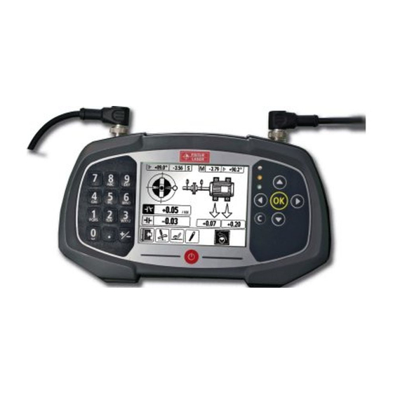
C H A P T E R Using the GO CHAPTER TWO GOALS At the conclusion of this chapter you will see how to: Perform all prealignment steps Correct vertical and horizontal misalignment with ƒ ƒ compound move Setup GO lasers correctly ƒ... - Page 10 U S I N G T H E F I X T U R L A S E R 1. SET UP THE FIXTURLASER GO Use the up/down & left/right arrow buttons ƒ on the right hand key pad to move the black 1.1 Mount the “S”...
- Page 11 U S I N G T H E F I X T U R L A S E R Center of post to center of post. 2.5 Enter this dimension into the display unit if different ƒ from the value displayed. 2.2 Enter this dimension into the display unit.
- Page 12 C H A P T E R 2.8 Enter this dimension into the display unit. Black highlight will move to the Measure icon in ƒ the lower right corner of the display. Third black highlighted box with ? mark. ƒ 3.
- Page 13 U S I N G T H E F I X T U R L A S E R boxes at the top of the display. highlight to the Exit Door icon . Press the “OK” If you do not, then the lasers are not within the ƒ...
- Page 14 C H A P T E R The angle and offset values ONLY determine the ƒ alignment condition. Angular Misalignment Offset Misalignment Mils per inch Mils .001/1" .001" Excellent Acceptable Excellent Acceptable 3600 0.3/1" 0.5/1" 1800 0.5/1" 0.7/1" 1200 0.7/1" 1.0/1"...
- Page 15 U S I N G T H E F I X T U R L A S E R Green LED indicates alignment in tolerance. It’s ƒ not necessary to adjust the foot values to zero. 7.2 Press the “OK” button to select. The GO is now “live”...
- Page 16 C H A P T E R Green LED should be on. ƒ 9.1 Use the left/right arrow buttons to move the black highlight to the Save icon if needed. 9.2 Press the “OK” button to Select. 9.3 Enter the name of the saved alignment. Use the left hand key pad to enter up to 17 ƒ...
-
Page 17: Chapter 3 Assisted Practice
C H A P T E R Assisted Practice CHAPTER THREE GOALS At the conclusion of this chapter, with a little help, you will be able to: Perform all prealignment steps Correct vertical and horizontal misalignment with ƒ ƒ compound move Setup GO lasers correctly ƒ... -
Page 18: Chapter 4 Student Practice-Aligning To 1800 Rpm Tolerances
C H A P T E R Student Practice Aligning to 1800 rpm Tolerances CHAPTER FOUR GOALS At the conclusion of this chapter, on your own, you will be able to: Perform all prealignment steps Correct vertical and horizontal misalignment with ƒ... -
Page 19: Chapter 5 Student Practice-Aligning To 3600 Rpm Tolerances
C H A P T E R Student Practice Aligning to 3600 rpm Tolerances CHAPTER FIVE GOALS At the conclusion of this chapter you will be able to: Perform all prealignment steps Correct vertical and horizontal misalignment with ƒ ƒ compound move Setup GO lasers correctly ƒ... -
Page 20: What Are Tolerances
C H A P T E R What Are Tolerances? CHAPTER SIX GOALS At the conclusion of this chapter, you will understand the: Difference between targets and tolerances ‘Zone of Good Alignment’ ƒ ƒ Relationship of speed to tolerances ƒ... - Page 21 W H A T A R E T O L E R A N C E S ? TOLERANCES ZONE OF GOOD ALIGNMENT Tolerances are the allowable deviations from the target values. The graph below shows a zone of acceptance for a 3600 So far our goal has been to make the movable shaft colinear RPM machine using angular and offset tolerances.
-
Page 22: Chapter 7 Go Settings
C H A P T E R GO Settings CHAPTER SEVEN GOALS At the conclusion of this chapter you will be able to: Change the date and time on the GO system Open the Memory Manager ƒ ƒ Select the measurement units Open/Delete existing files ƒ... - Page 23 To change field, use left/right arrows as needed ƒ will be discussed in this chapter. To exit, press “OK” (entire Date setting highlighted) ƒ 1. GLOBAL SETTINGS FIXTURLASER GO Global settings are accessed from the start screen ƒ Time ƒ...
- Page 24 2.4 Press the up arrow to move the black highlight over the desired setting From top to bottom: ƒ 2.6 Press “OK” to exit back to start screen. 3. MEMORY MANAGER FIXTURLASER GO The memory management application is accessed ƒ from the start screen.
- Page 25 ƒ to the bottom row of icons, the file cabinet will be 4. TRANSFERRING DATA TO PC, highlighted. FIXTURLASER GO Saved files in .BMP format may be transferred to a PC ƒ via provided USB cable The GO must be at the start screen to transfer data ƒ...
-
Page 26: Chapter 8 Student Practice-Checking For Softfoot Using The Go
C H A P T E R Student Practice Checking for Softfoot Using the GO CHAPTER EIGHT GOALS At the conclusion of this chapter you will be able to: Use the SoftCheck™ function to measure and correct softfoot... - Page 27 Never ‘feather’ shims out to fix an angled foot. It is unlikely the angular correction will be duplicated when shim piles are changed out during the alignment. Using The Fixturlaser GO To Check Softfoot (Softcheck 1. SET UP THE FIXTURLASER GO 1.4 Turn the unit on by pressing the red button at the...
- Page 28 C H A P T E R Use left hand keypad to enter the value as a ƒ decimal. 1.7 Aim the lasers. The sensors will be on different elevations. ƒ Open the green latches on either sensor and ƒ slide up or down to aim the laser into the light grey band on the opposite sensor.
- Page 29 C H E C K I N G F O R S O F T F O O T Third black highlighted box with ? mark. ƒ Use left hand keypad to enter the value as a ƒ decimal. 2.9 Press the “OK” button on the right-hand key pad to accept the value.
- Page 30 C H E C K I N G F O R S O F T F O O T A warning icon will appear if the sensors are not at the Values displayed are the approximate soft foot at ƒ ƒ...
-
Page 31: Chapter 9 Student Practice-Using Thermal Targets
C H A P T E R Student Practice Using Thermal Targets CHAPTER NINE GOALS At the conclusion of this chapter you will be able to: Understand why some machines are intentionally misaligned ƒ Understand the difference between growth and targets ƒ... - Page 32 U S I N G T H E R M A L T A R G E T S TARGETS 1.3 Select the larger boxes under the feet to enter target values for the stationary and/or moveable feet. Some equipment moves from its off-line (cold) position when it If the machine grows vertically (a positive amount), the is on-line and operating (hot).
-
Page 33: Chapter 10 Student Practice-Using The Clock Method
C H A P T E R Student Practice Using the Clock Method CHAPTER TEN GOALS At the conclusion of this chapter you will be able to: Describe difference between the Tripoint and Clock methods ƒ Identify when you should use the clock method ƒ... - Page 34 Remember, it is best to rotate the shafts as much as possible. Rotation of less than 60° may make for a difficult alignment. The steps below will walk us through a standard Clock method alignment, taking readings at 9 o’clock, 3 o’clock and 12 o’clock. Using The Fixturlaser GO Clock Method 1. SET UP THE FIXTURLASER GO 1.1 Mount the “S”...
- Page 35 U S I N G T H E C L O C K M E T H O D Open the green latches on either sensor and ƒ slide up or down to aim the laser into the light grey band on the opposite sensor. Adjusting one sensor will adjust both.
- Page 36 C H A P T E R Fourth black highlighted box with ? mark. 3.3. Select the machine RPM using up/down arrow ƒ buttons to highlight the correct RPM. Press the 2.12 Press the “OK” button on the right-hand keypad to “OK”...
- Page 37 U S I N G T H E C L O C K M E T H O D 4.1 Rotate the sensors to 9:00. 4.4 Press the “OK” button to register the 2nd measurement. The “S” and “M” values will not change. ƒ...
- Page 38 C H A P T E R Angular Misalignment Offset Misalignment Mils per inch Mils .001/1" .001" Excellent Acceptable Excellent Acceptable 3600 0.3/1" 0.5/1" 1800 0.5/1" 0.7/1" Rotate the sensors to the 3:00 position ƒ 1200 0.7/1" 1.0/1" 1.0/1" 1.5/1" The RPM you select in the tolerance table determines ƒ...
- Page 39 U S I N G T H E C L O C K M E T H O D 9.1 Use the left/right arrow buttons to move the black highlight to the Save icon if needed. 9.2 Press the “OK” button to select. 9.3 Enter the name of the saved alignment.
- Page 40 T R A I N I N G M A N U A L www.vibralign.com 800-379-2250 530 G Southlake Blvd. Richmond, VA 23236 Phone (804) 379-2250 Fax (804) 379-0189 ©2010 Vibralign, Inc.
Need help?
Do you have a question about the Fixturlaser Go and is the answer not in the manual?
Questions and answers