Table of Contents

Summary of Contents for Schrack AVARA Sentryum USS3M Series
- Page 1 User Manual UNINTERRUPTIBLE POWER SUPPLY Series AVARA Sentryum SERIE USS3M - USS3T 10 - 20 kVA 1 - 3 phase input / 1 phase output (USS3M..) 3 phase input / 3 phase output (USS3T..) On Line / Double Conversion (VFI) Technology...
- Page 2 NTRODUCTION For information with regards to the use of, and to ensure that you obtain the best performance from your UPS. This manual should be stored near to the UPS and must be READ PRIOR TO PERFORMING ANY OPERATIONS UPON IT. NOTE: Some of the images in this document are provided as a guideline only, and they may not accurately reproduce the depicted product components.
-
Page 3: Table Of Contents
SUMMARY GLOSSARY OF ACRONYMS PRESENTATION USS3T – USS3M 10/15/20 ESCRIPTION ENERAL VIEWS OMMUNICATION OMMUNICATION PORTS UPS OPERATION PERATING MODES ON LINE MODE MODE SMART ACTIVE MODE FREQUENCY CONVERTER MODE STAND BY OFF MODE PERATING STATUS ORMAL TAND BY WITH BATTERY CHARGER OFF TAND BY WITH BATTERY CHARGER ON ATTERY WORKING... - Page 4 YSTEM HOME PAGE YSTEM MEASUREMENTS YSTEM STATUS NTRIES OMMAND PANEL System Off/On command Bypass command Battery Test command Battery Charger On command LARM TEMPORARY SUPPRESSION LOBAL SYSTEM INFORMATION AIN SETUP PAGE Language setting Display setting System clock Screen saver and buzzer Change password YSTEM LOG PAGE “E...
- Page 5 YSTEM N DIRECT COMMAND YSTEM N COMMAND VIA BATTERY TART PERATIONS CHECKS ATTERY ATTERY ORKING ORCED YPASS WITCHING THE YSTEM FROM INE TO ANUAL YPASS MERGENCY ANUAL YPASS PROCEDURE ESTORE THE ODE AFTER ANUAL YPASS OAD ON STATIC BYPASS AFTER ANUAL YPASS YSTEM...
- Page 6 TROUBLESHOOTING GUIDE PREVENTIVE MAINTENANCE NTRODUCTION ATTERIES APACITORS TECHNICAL DATA TABLE...
-
Page 7: Glossary Of Acronyms
GLOSSARY OF ACRONYMS Acronym ITEM Description CPT Version UPS model type ACT Version UPS model type XTD Version UPS model type USS3T Three phase output voltage UPS Three Phase Version USS3M Single phase output voltage UPS Single Phase Version Extended Runtime Version with high battery charging current capability Version with separated lines for Mains and Bypass input Dual Input... -
Page 8: Presentation
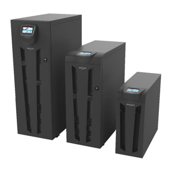
PRESENTATION USS3T – USS3M 10/15/20 USS3T – USS3M UPS Systems are intended to ensure a perfect supply voltage for the equipment connected to it, both with and without a power supply network. Once connected and powered, the system generates an alternating sinusoidal voltage, with stable amplitude and frequency, regardless of surges and/or variations affecting the electrical supply. -
Page 9: Description
ESCRIPTION The purpose of a UPS is to provide a perfect power supply voltage for the devices connected to it, irrespective of whether the mains power supply is present or not. Once connected and powered, the UPS generates a sinusoidal alternating voltage with a stable amplitude and frequency, regardless of any changes and/or variations occurring on the electricity network. -
Page 10: General Views
ENERAL VIEWS FRONT REAR Touch screen display Slot for optional accessory communication cards UPS status LED Internal battery fuse holders (SWBATT) Battery start button (COLD START) Mains input switch (SWIN) Communication ports (R.E.P.O., IN/OUT SIGNAL) Output switch (SWOUT) Communication ports (USB, SERIAL) Manual bypass switch (SWMB) Parallel card (optional) Brake plate... -
Page 11: Act
FRONT REAR Touch screen display Internal battery fuse holders (SWBATT) UPS status LED Mains input switch (SWIN) Battery start button (COLD START) Output switch (SWOUT) Communication ports (R.E.P.O., IN/OUT SIGNAL) Manual bypass switch (SWMB) Communication ports (USB, SERIAL) Brake plate Parallel card (optional) Bypass input switch (SWBYP) Slot for optional accessory communication and contacts cards... -
Page 12: Xtd
FRONT REAR Touch screen display Internal battery fuse holders (SWBATT) UPS status LED Mains input switch (SWIN) Battery start button (COLD START) Output switch (SWOUT) Communication ports (R.E.P.O., IN/OUT SIGNAL) Manual bypass switch (SWMB) Communication ports (USB, SERIAL) Brake plate Parallel card (optional) Bypass input switch (SWBYP) Slot for optional accessory communication and contacts cards... -
Page 13: Communication
OMMUNICATION OMMUNICATION PORTS The communication ports are situated in the top section at the rear of the UPS. Refer to the following image for the exact location of each port. Parallel board: R.E.P.O / IN / OUT: An optional parallel board can be fitted into the UPS these are digital inputs and dry contact outputs in order to enable up to eight three phase units available to the user to perform various functions. -
Page 14: Ups Operation
UPS OPERATION PERATING MODES The UPS can be configured for different operating modes. The following operating modes as listed below may be selected. ON LINE MODE When in ON LINE mode, the system operates in ON LINE double conversion. This mode provides maximum protection for the load. During operation the energy coming from the electrical supply network (AC), is converted into a clean and stable output. -
Page 15: Battery Working
ATTERY WORKING When the UPS is supplying the output with the batteries present, if the mains supply network falls outside the pre-set tolerances, for example in case of a blackout, voltage or frequency disturbance, the system automatically switches to BATTERY OPERATING STATUS and draws power from the batteries to support the load. -
Page 16: Display
DISPLAY VERVIEW The UPS is equipped with a 5’’ touch screen colour display, through which, amongst others, it is possible to: view the status of the system; switch on / switch off the system, activate a battery test and perform bypass operation commands; ... -
Page 17: Icons And Symbols
CONS AND SYMBOLS System input/mains status % Battery charge level System output status % Phase 1 load level Bypass status % Phase 2 load level Battery status % Phase 3 load level System status Manual bypass switch closed (SWMB) In general, the color and the shape of the icons provide instant information to the status of the system. Grey: communication lost (Com-Lost) Orange: anomaly Light blue: normal status... -
Page 18: Active Text Areas
CTIVE TEXT AREAS System Status: area of the display reserved for the description of the system status. If the UPS is in NORMAL MODE this area will indicate the current operating mode, or another operational system state. NORMAL MODE means that the UPS is working in the expected operational state for the configured operating mode (e.g. -
Page 19: System Home Page
YSTEM HOME PAGE The home page provides a schematic view of the overall operating condition of the system. It is possible to interact with the system and access further information via the icons . Depending on the current state of the system, this page may assume different appearances as shown in the examples below. The user can return on the home page at any time by tapping the “Home”... - Page 20 Home page displaying BATTERY WORKING status. Home page displaying MANUAL BYPASS SWITCH CLOSED. Home page with alarm drop-down list opened.
-
Page 21: System Measurements
YSTEM MEASUREMENTS The pages that display the main electrical values of the system can be accessed through the icons in the Home page: Pressing one of the four section icons Input (1), Bypass (2), Battery (3), Output (4) will open the relative measurements page. Mains Input page: displays the status and the parameters relating to the system input. -
Page 22: System Status
Battery status page: displays the status and the parameters related to the system batteries. On the left are shown the voltages of the positive (B+) and negative (B-) battery banks. The battery currents, displayed on the right, have a positive symbol if the UPS is working from battery, whilst the symbol is negative if the battery is under charge. The charge level is estimated by an algorithm that computes the energy flowing to and from the batteries and the voltage level. - Page 23 Switch status page: displays the status of the UPS internal switches and the optional external switches. The external switch auxiliary contacts must be connected to the digital inputs and programmed using the configuration software. Sensor status page: displays the temperature of the system and of the power heatsinks. The Ext-Bat value will be shown if a Battery Cabinet external temperature sensor is installed and set by the configuration software.
-
Page 24: Menu Entries
NTRIES The main menu can be accessed through the menu icons displayed on the right. Access level selection. Command launcher The icon changes depending on the preset access level Buzzer toggle button UPS info Settings menu Event log OMMAND PANEL To access the Command Panel, tap the Command launcher icon. -
Page 25: Bypass Command
A confirmation of the action is required for some of the commands. Press “OK” to confirm the operation. System on confirmation After pressing the OK button in the confirmation window, a bar will show the progress of the command completion. Progress bar during a system start-up sequence. -
Page 26: Battery Test Command
ATTERY EST COMMAND Battery commands page USS3T - USS3M UPS are equipped with a built-in battery test function. This function forces the UPS to work from battery and monitors the battery voltage under load to check if the battery is healthy. NOTE: the UPS switches to battery just for the short time needed to execute the battery test and only when the main supply is present as backup, therefore the battery charge level and the load safety are not compromised. - Page 27 This page displays the following information: Model: the Manufacturer’s part number. Serial number: the UPS identification number. Nominal power (VA): the UPS rated apparent power, in VA. Nominal power (W): the UPS rated active power, in W. ...
-
Page 28: Language Setting
ANGUAGE SETTING Enables the language configuration of the system menus. Tap the flag to select the language. Language configuration page ISPLAY SETTING Display configuration pages To save any configuration setting: Press the Save icon and confirm to store any new values. -
Page 29: System Clock
YSTEM CLOCK This page enables the user to configure the date and the time of the system. System clock configuration page. NOTE: When the system is first switched on or if the system has been switched off for a long period, it may be necessary to set date and time again. -
Page 30: Change Password
HANGE PASSWORD Access level selection page. For more information refer to the “Access users level” paragraph. YSTEM LOG PAGE Tap the Event Log icon to access the system log. In this page, the user can view the UPS event history. The rise and fall indicate respectively when the alarm related to the event happened and when it was cleared. -
Page 31: Expert " Level
“E ” XPERT LEVEL It is possible to access the “Expert” level in which the general UPS configurations are enabled. The “Expert” level is reserved only for trained personnel with knowledge of the UPS parameter configuration. To access to the “Expert” level, expand the drop-down menu in the Home page and tap level selection icon. A password is required. -
Page 32: General System Settings
ENERAL SYSTEM SETTINGS Only “Expert” level users can access this page. It enables additional system configuration. With the “Expert” access level enabled, tap the Main Setup icon. Main setup page in the “Expert” mode (with additional “General” icon) General system settings pages ENERAL CONFIGURATION Enables various options for the UPS: General configuration page 1: operating mode configuration... -
Page 33: Auto Power Off
UTO POWER OFF If, during battery operation, the percentage of the load powered by the system falls below the selected threshold, after 40 seconds the system automatically switches off if the function is enabled; the system continues to function normally via battery if the function is disabled [Default →... -
Page 34: Voltage Setting
OLTAGE SETTING To set the desired output voltage, tap on the corresponding select box. The first selection is customisable by writing the voltage in the text box. If a low output voltage is selected, the percentage of power derating is shown on the right. The modification can be done also when the system is ON LINE. -
Page 35: Battery Configuration
ATTERY CONFIGURATION This page displays the battery capacity. The configuration of the internal and the external battery (Ah) is not available by the display. To set the internal and the external battery capacity it is necessary to use the configuration software (reserved for service personnel only). -
Page 36: Access Users Level
CCESS USERS LEVEL It is possible to control access user levels, by setting a password for each one. “User” level “PowerUser” level “Expert” level To set or change a level password expand the drop-down menu in the Home page and tap the Main Setup icon. -
Page 37: Access Level Selection
CCESS LEVEL SELECTION This page enables the selection of the access level for the user operating the UPS. If preset, a safety password may be requested, based on the selected level. Expand the drop-down menu in the Home page and touch the access level selection icon. Access level selection page If some of this icon is not visible, it means that the password protection is not set for this access level. -
Page 38: Status Led
TATUS Below the touch screen display, a back illuminated bar will inform the user at a glance the status of the UPS. The following are the various colour-states and their respective meanings. Light blue (pulsing): Normal operation Dark blue: Bypass operation No anomalies are present, and the system is working in the The system is working from temporary bypass. -
Page 39: Configuring The Ups From Display
ONFIGURING THE FROM DISPLAY Configurations which can be modified by the user from the display are listed in Table 2 (below). ACCESS FUNCTION DESCRIPTION DEFAULT POSSIBLE CONFIGURATIONS LEVEL English Italian Selection of the mimic German “PowerUser” Language English panel language ... -
Page 40: Default Configuration Of The Input / Output Signals
EFAULT CONFIGURATION OF THE INPUT OUTPUT SIGNALS UTPUT SIGNALS CONFIGURATION FACTORY DEFAULT Table 4 (below) lists the default configuration of the output signals. OUTPUT FUNCTION DESCRIPTION Load on bypass with closed contact between pin 2 and pin 4; OUT 1 Load on Bypass ... -
Page 41: Operative Procedures
OPERATIVE PROCEDURES RELIMINARY PERATIONS Before powering the UPS and starting the operative procedures, in order to avoid any system damage, follow the operations below. Visual check of the connection Check that all the isolators are open. Check that all the connections have been made strictly following the indications given in the “Installation manual”. ... -
Page 42: System O N Direct Command
YSTEM N DIRECT COMMAND Close the mains input switch (SWIN), the bypass input switch (SWBYP) if present, and the battery fuse holder (SWBATT). Check that the display turns on and the UPS enters into the "STAND-BY WITH CB OFF" mode. ... -
Page 43: System O N Command Via Battery (Cold Start )
YSTEM N COMMAND VIA BATTERY TART For the COLD START button location, please refer to the “General views” chapter. Note: Avoid turning on the system from battery if the battery charge status and/or the autonomy information are unknown. Close the battery fuse holders. ... -
Page 44: Operations Checks
PERATIONS CHECKS Follow the procedures below to verify that the UPS works properly during battery working and automatic bypass switching. These operations must be executed with the UPS in ON LINE mode. ATTERY Press the “Battery Test” icon to execute the command. A confirmation is required. -
Page 45: Switching The System From O N -Line To Manual Bypass
WITCHING THE YSTEM FROM INE TO ANUAL YPASS The following operations have to be performed in order to switch the UPS load to “Manual Bypass”. NOTE: if the Bypass line is not present, the manual bypass operation will cut off power to the load. With the SWMB closed, the load is supplied directly from the bypass line. -
Page 46: Restore The O N Line Mode After Manual Bypass
ESTORE THE ODE AFTER ANUAL YPASS The following operations have to be performed in order to switch the UPS from “Manual Bypass” to ON LINE mode: Switch on the Mains (SWIN), the Bypass (SWBYP) and Battery input lines (SWBATT) and close the Output switch (SWOUT). ... -
Page 47: Load On Static Bypass After Manual Bypass
OAD ON STATIC BYPASS AFTER ANUAL YPASS The following operations are to be performed in order to switch the UPS from “Manual Bypass” to “Load forced on bypass” status: Switch on the Mains (SWIN), Bypass (SWBYP) and battery input lines (SWBATT) and close the output switch (SWOUT). ... -
Page 48: Options
OPTIONS XTERNAL BATTERY CABINET All the UPS within the USS3T - USS3M family can be supplied with matching external Battery Cabinets. These can be supplied by the factory or by a local supplier subject to being compliant with the statement below. Read the Battery Cabinet manual before connecting the batteries. -
Page 49: Battery Room Ventilation
CHECKING INSTALLATION: NOTE: the size of the fuses fitted will depend on the type of Battery Cabinet installed. If the Battery Cabinet is supplied by our Company, make sure to have the correct fuse for the given UPS size (refer to Battery Cabinet manual). -
Page 50: External Battery Temperature Probe
XTERNAL BATTERY TEMPERATURE PROBE An optional temperature probe kit provides the USS3T - USS3M UPS with the ability to monitor the temperature within a separate Battery Cabinet via the terminals located on the power terminal area, identified as “EXT T_BATT” (marked as 3 and 4, refer to the “Power connection details”... -
Page 51: Remote Maintenance Bypass
EMOTE MAINTENANCE YPASS An additional maintenance bypass may be installed within (or in addition to) the main switchboard, for example, to enable the UPS to be replaced without interrupting the power supply to the load, in this case respect the following details: It is mandatory to connect the "SERVICE BYPASS"... -
Page 52: External Sync Kit
DIAGRAM SHOWING REMOTE INSTALLATION OF THE MAINTENANCE BYPASS (USS3M MODEL) Main switchboard Internal connections of the UPS Programmable IN/OUT port (to be configured via the configuration software) INPUT switch: for correct sizing refer to the "Internal Protective Devices” paragraph OUTPUT switch: for correct sizing refer to the "Internal Protective Devices” paragraph, equipped with a normally closed auxiliary contact SERVICE BYPASS switch: for correct sizing refer to the "Internal Protective Devices”... -
Page 53: Internal Transformer
NTERNAL TRANSFORMER (OPTIONAL) VERSION OF THE UPS SERIES DIFFERS FROM THE STANDARD VERSION IN THAT IT INCLUDES AN ISOLATION TRANSFORMER INSTEAD OF THE INTERNAL BATTERIES. This series of UPS (available only in a dedicated chassis of the XTD version), is equipped with an isolation transformer connected to the UPS output terminals. -
Page 54: Remote Panel
EMOTE PANEL The remote panel enables the remote monitoring of the UPS and gives a real time detailed summary of the machine status. The device ensures that the operator can monitor the electrical values of the mains power, outputs, batteries, etc. and locate any alarm conditions. For further information regarding the connection and use of this device, please refer to its dedicated user manual. -
Page 55: Status / Alarm Codes
STATUS / ALARM CODES Using a sophisticated self-diagnostic system, the UPS can check and indicate on the display its status and any errors and/or faults that have occurred during its operation. When a problem arises, the UPS signals the event by showing the code and corresponding type of alarm on the display. -
Page 56: Warning
ARNING Messages that refer to a specific configuration or operation of the UPS. CODE DESCRIPTION Battery low warning Shutdown active Shutdown imminent Bypass disabled Synchronisation disabled Service UPS Service Battery Table 9 – UPS warning list NOMALIES Minor problems that do not stop the operation of the UPS, but affect its performance or inhibit the use of some of its functions. CODE DESCRIPTION Configuration data corrupted... -
Page 57: Faults
AULTS Faults are problems more critical than “Anomalies” in that, if they persist, they may bring the UPS to a stop. CODE DESCRIPTION Internal communication error Mains phases reversed Input fuse/contact fault L1 Input fuse/contact fault L2 Input fuse/contact fault L3 Input contact short cct L1 Input contact short cct L2 Input contact short cct L3... -
Page 58: Locks
OCKS Locks indicate a breakdown of the UPS or one of its parts. Locks are normally preceded by an alarm signal. In the event of a fault and resultant breakdown of the inverter, the inverter will be switched off and the load will be powered by the bypass line (this procedure is excluded for breakdowns caused by high and persistent overloads and by short circuits). - Page 59 TROUBLESHOOTING GUIDE Irregular operation of the UPS is very often not an indication of a fault but is simply caused by simple problems or distractions. We therefore recommend you consult the table here below, which provides some information that will help you to solve the most common problems.
- Page 60 PROBLEM POSSIBLE CAUSE SOLUTION THE BATTERIES ARE THE ALARM LIST DISCHARGED; THE UPS Wait for the batteries to recharge or force power on from the SHOWS THE CODE WAITS FOR THE BATTERY “Command panel” VOLTAGE EXCEEDING THE SET THRESHOLD THE JUMPER IS MISSING FROM THE R.E.P.O.
- Page 61 PROBLEM POSSIBLE CAUSE SOLUTION Remove the load. Insert the maintenance bypass THE ALARM LIST SHOWS (SWMB), and turn the UPS off and then on again. Switch FAULTY LOADS APPLIED ONE OR MORE OF THE off the maintenance bypass. If the problem persists, call FOLLOWING CODES: your local service centre F11, F13, F14, F15, F16, F17,...
- Page 62 PREVENTIVE MAINTENANCE NTRODUCTION Our UPS are designed and produced for long life even under the severest operating conditions. Remember however that they are electrical power equipment items and as such are in need of periodic checks. Besides, some components have a life cycle of their own and must therefore be checked at regular intervals and may need to be replaced, due to the conditions;...
- Page 63 TECHNICAL DATA TABLE USS3T – USS3M - from 10 to 20 kVA INPUT Three-phase 400 (3PH + N) (USS3T/USS3M) Rated voltage [V] Single-phase (USS3M) 230 (PH + N) Rated frequency [Hz] 50-60 20 @ 100% load Accepted tolerance for input voltage [%] -40 +20 @50% load Accepted tolerance for input frequency [Hz] 40-72...
- Page 64 MAN_AVARA Sentryum_USS3T_USS3M_10-20kVA_EN_2020_04_04_0MNS3TK10NPENUD.docx 0MNS3TK10NPENUD...
Need help?
Do you have a question about the AVARA Sentryum USS3M Series and is the answer not in the manual?
Questions and answers