
Related Manuals for Marley 440 Series

Summary of Contents for Marley 440 Series
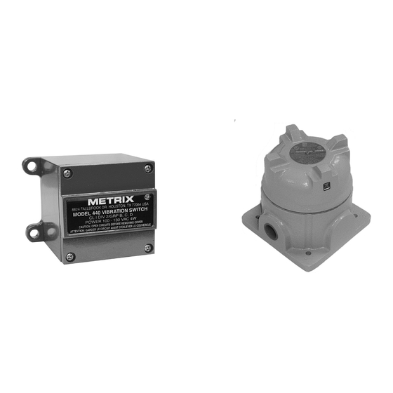
- Page 1 u s e r m a n u a l 440 - 450 vibration switch I N STA L L AT I O N - O P E R AT I O N - M A I N T E N A N C E Z 0 5 9 2 8 2 2 _ A I S S U E D 0 6 / 2 0 17 R EAD AN D U N DE R STAN D TH IS MAN UAL PR IOR TO OPE RATI NG OR SE RVICI NG TH IS PRODUCT.
-
Page 2: Table Of Contents
contents Section 1 - General Description ................3 Section 2 - Mechanical Installation ................8 Section 3 - Electrical Wiring ...................9 Section 4 - Control Settings ................13 Section 5 - System Block Diagram ..............14 Wiring Diagram ......................15... -
Page 3: Section 1 - General Description
description Introduction The single set point model contains one trip limit for shutdown. The optional dual set point model contains two independent trip limits; one for alarm and one for shutdown. Shutdown and Alarm trip is set in velocity. In addition, a 4-20 mA output proportional to vibration level is provided. - Page 4 description point controls permit adjusting set points to known values of vibration level. Shutdown and Alarm set point range is in velocity. Alarm setpoint is calibrated 10% to 90% of shutdown setpoint. 3—4-20 mA output provides continuous monitoring capability on a millimeter or a programmable controller for data logging or alarm.
- Page 5 description Panel Control Test position sets in minimum set point so that any vibration will cause trip condition. Light will come on immediately, and trip will occur after duration of the time delay, proving that the complete system is operational. If test position is maintained for less than the duration of the time delay, trip will not occur, thus permitting system test without shutdown.
- Page 6 description Remote Reset—Connection between terminals 5 and 6 latches triac output in alarm state after set point is exceeded. Opening the connection will reset the output to non-alarm state. Set Point Accuracy— ± 10% of setting with repeatability of ± 2%. Circuitry utilizes RMS detector.
- Page 7 description Mechanical Relay Option— SPDT Version - 8 amp at 250 VAC or 24 VDC DPDT Version - 1. DPDT, 2 amp each half at 250 VAC or 24 VDC 2. SPDT, 8 amp each half at 250 VAC or 24 VDC. The N.O./N.C.
-
Page 8: Section 2 - Mechanical Installation
installation Mechanical Installation Orientation The sensitive vibration “measuring” axis is perpendicular to the base of the unit (vibration switch or transducer). Always mount the unit such that the desired vibration of the equipment being monitored will occur along this axis. Mounting Surface Choose or fabricate a solid (rigid) surface (on the equipment being monitored) to mount the vibration switch or transducer. -
Page 9: Section 3 - Electrical Wiring
installation To assure compatibility with EMC standards, any signal level wiring such as transducer, reset, lockout, or 4-20 mA wiring should utilize shielded cable in EMI proof conduit, separate from any power wiring. The signal conduit and power-wiring conduit can be connected at the 440-cable entry via a “T” fitting. Sealing In 440 installations where temperature and humidity conditions vary around the dew point, it is important that the cover plate be evenly and firmly fastened... - Page 10 installation For 440/450 Models Using Mechanical Relay Remote Reset 4-20mA Analog Output Common Not Used Shutdown N.C. Not Used Shutdown Common Input Signal (Optional) Shutdown N.O. Alarm N.C. AC Input Alarm Common Power Alarm N.O. Alarm circuit is not used for SR versions. AC Power—Connect a grounding wire to the grounding screw provided in Note the switch.
- Page 11 installation Functional Description and Installation Considerations Alarm or Shutdown—Units with Triacs (identified by Model No. 440DR- 2X01-XXXX). Maximum ratings for the solid state relays used for alarm and shutdown are as follows: Continuous Current Surge and Overload (Duty Cycle Less Than 1%) 1 Second 25 A 16 Millisecond...
- Page 12 Special Considerations Light Loads—The solid state triacs used in the standard 440 series are a special high transient immunity, medium power type. Off state leakage is 1 mA max and should not create any problems, even when interfaced with a load as light as a programmable controller.
-
Page 13: Section 4 - Control Settings
installation (50 mA or less) a 2K-ohm 10 watt power resistor is recommended. D.C. Loads with Triacs—Although most applications use AC input power and AC on the triac outputs (alarm and shutdown), these triacs may be used in DC applications providing minimum loading requirements are met. When DC is used, a triac will automatically latch in the “on”... -
Page 14: Section 5 - System Block Diagram
installation The time a vibration must be above set point before trip occurs is individually adjustable for shutdown and alarm from 2 to 15 seconds. To readjust the time delay, turn the shutdown set point (or alarm set point for alarm time delay) knob CCW until the LED illuminates. -
Page 15: Wiring Diagram
installation reference, the shutdown LED is illuminated. If the voltage level stays above the reference for the duration of the time delay, an output trip occurs and the shutdown solid-state relay will trip. Alarm trip is derived in much the same manner, branching from the output of the RMS to DC stage. - Page 16 440 - 450 vibration switch U S E R M A N UA L SPX COOLING TECHNOLOGIES, INC. 7401 WEST 129 STREET Z0592822_A (07-1273) ISSUED 06/2017 OVERLAND PARK, KS 66213 USA COPYRIGHT © 2017 SPX CORPORATION In the interest of technological progress, all products are subject to design 913 664 7400 | spxcooling@spx.com and/or material change without notice.
Need help?
Do you have a question about the 440 Series and is the answer not in the manual?
Questions and answers