
Related Manuals for VIPA IM 053MT

Summary of Contents for VIPA IM 053MT
- Page 1 VIPA System SLIO IM | 053-1MT00 | Manual HB300E_IM | RE_053-1MT00 | Rev. 11/28 July 2011...
- Page 2 Copyright © VIPA GmbH. All Rights Reserved. This document contains proprietary information of VIPA and is not to be disclosed or used except in accordance with applicable agreements. This material is protected by the copyright laws. It may not be reproduced, distributed, or altered in any fashion by any entity (either internal or external to VIPA), except in accordance with applicable agreements, contracts or licensing, without the express written consent of VIPA and the business management owner of the material.
-
Page 3: Table Of Contents
Manual VIPA System SLIO Contents Contents About this manual ..................1 Safety information ..................2 Chapter 1 Basics and Assembly ............. 1-1 Safety Information for Users..............1-2 System conception ................1-3 Dimensions ..................1-6 Installation .................... 1-7 Demounting and module exchange ............ 1-10 Wiring.................... - Page 4 Manual VIPA System SLIO Contents HB300E - IM - RE_053-1MT00 - Rev. 11/28...
-
Page 5: About This Manual
Overview Chapter 1: Basics and Assembly The focus of this chapter is on the introduction of the VIPA System SLIO. Here you will find the information required to assemble and wire a controller system consisting of System SLIO components. Besides the dimensions the general technical data of System SLIO will be found. - Page 6 Manual VIPA System SLIO About this manual This manual describes the IM 053-1MT00 of the System SLIO from VIPA. Objective and It contains a description of the structure, project engineering and contents deployment. This manual is part of the documentation package...
-
Page 7: Safety Information
Manual VIPA System SLIO Safety information Safety information The System SLIO is constructed and produced for: Applications conforming with • communication and process control specifications • general control and automation applications • industrial applications • operation within the environmental conditions specified in the technical data •... - Page 8 Manual VIPA System SLIO Safety information HB300E - IM - RE_053-1MT00 - Rev. 11/28...
-
Page 9: Chapter 1 Basics And Assembly
Chapter 1 Basics and Assembly Chapter 1 Basics and Assembly The focus of this chapter is on the introduction of the VIPA System SLIO. Overview Here you will find the information required to assemble and wire a controller system consisting of System SLIO components. -
Page 10: Safety Information For Users
Manual VIPA System SLIO Chapter 1 Basics and Assembly Safety Information for Users VIPA modules make use of highly integrated components in MOS- Handling of Technology. These components are extremely sensitive to over-voltages electrostatic that can occur during electrostatic discharges. -
Page 11: System Conception
Manual VIPA System SLIO Chapter 1 Basics and Assembly System conception System SLIO is a modular automation system for assembly on a 35mm Overview mounting rail. By means of the peripheral modules with 2, 4 or 8 channels this system may properly be adapted matching to your automation tasks. - Page 12 Manual VIPA System SLIO Chapter 1 Basics and Assembly Each periphery module consists of a terminal and an electronic module. Periphery modules Terminal module Electronic module Terminal module The terminal module serves to carry the electronic module, contains the backplane bus with power supply for the electronic, the DC 24V power section supply and the staircase-shaped terminal for wiring.
- Page 13 Manual VIPA System SLIO Chapter 1 Basics and Assembly Accessories Shield bus carrier The shield bus carrier serves to carry the shield bus (10mm x 3mm) to connect cable shields. Shield bus carriers, shield bus and shield fixings are not in the scope of delivery.
-
Page 14: Dimensions
Manual VIPA System SLIO Chapter 1 Basics and Assembly Dimensions Dimensions bus coupler 76.5 48.5 Dimensions periphery module 76.5 12.9 Dimensions electronic module 12.9 Dimensions in mm HB300E - IM - RE_053-1MT00 - Rev. 11/28... -
Page 15: Installation
Manual VIPA System SLIO Chapter 1 Basics and Assembly Installation There is a locking lever at the top side of the terminal module. For Functional mounting and demounting this locking lever is to be turned upwards until principle this engages audible. - Page 16 Manual VIPA System SLIO Chapter 1 Basics and Assembly The modules were directly be mounted to the mounting rail and so Mounting connected to the backplane bus and the power supply for the electronic Proceeding and power section. Up to 64 modules may be mounted. Please consider here that the sum current of the electronic power supply does not exceed the maximum value of 3A.
- Page 17 Manual VIPA System SLIO Chapter 1 Basics and Assembly • Mounting Mount the periphery modules you want. periphery modules Clack • After mounting the whole system, to protect the backplane bus Mounting the bus cover connectors at the last module you have to mount the bus cover, now.
-
Page 18: Demounting And Module Exchange
Manual VIPA System SLIO Chapter 1 Basics and Assembly Demounting and module exchange With demounting and exchange of a module, head module (e.g. bus Proceeding coupler) or a group of modules for mounting reasons you have always to remove the electronic module of the just mounted right module. After the mounting it may be plugged again. - Page 19 Manual VIPA System SLIO Chapter 1 Basics and Assembly • For mounting turn the locking lever of the module to be mounted upwards. • To mount the module put it to the gap between the both modules and push it, guided by the stripes at both sides, to the mounting rail.
- Page 20 Manual VIPA System SLIO Chapter 1 Basics and Assembly • For mounting turn all the locking lever of the head module to be mounted upwards. • To mount the head module put it to the left module and push it, guided by the stripes, to the mounting rail.
- Page 21 Manual VIPA System SLIO Chapter 1 Basics and Assembly • Pull the module group forward. • For mounting turn all the locking lever of the module group to be mounted upwards. • To mount the module group put it to the gap between the both modules and push it, guided by the stripes at both sides, to the mounting rail.
-
Page 22: Wiring
Manual VIPA System SLIO Chapter 1 Basics and Assembly Wiring Terminals with spring clamp technology are used for wiring. The spring Connectors clamp technology allows quick and easy connection of your signal and supply lines. In contrast to screw terminal connections this type of connection is vibration proof. - Page 23 Manual VIPA System SLIO Chapter 1 Basics and Assembly Standard wiring SysDC5V max. 3A DC24V max. 10A DC24V DC24V (1) DC 24V for power section supply I/O area (max 10A) (2) DC 24V for electronic power supply bus coupler and I/O area...
- Page 24 If the 10A for the power section supply is no longer sufficient, you may use Deployment of the the power module from VIPA with the order number 007-1AB00. So you power modules have also the possibility to define isolated groups.
- Page 25 Manual VIPA System SLIO Chapter 1 Basics and Assembly To attach the shield the mounting of shield bus carriers are necessary. Shield attachment The shield bus carrier (available as accessory) serves to carry the shield bus to connect cable shields.
-
Page 26: Trouble Shooting - Leds
Manual VIPA System SLIO Chapter 1 Basics and Assembly Trouble shooting - LEDs Each module has the LEDs RUN and MF on its front side. Errors or General incorrect modules may be located by means of these LEDs. In the following illustrations flashing LEDs are marked by ☼. -
Page 27: Installation Guidelines
Manual VIPA System SLIO Chapter 1 Basics and Assembly Installation guidelines The installation guidelines contain information about the interference free General deployment of System SLIO. There is the description of the ways, interference may occur in your control, how you can make sure the electromagnetic digestibility (EMC), and how you manage the isolation. - Page 28 Manual VIPA System SLIO Chapter 1 Basics and Assembly In the most times it is enough to take care of some elementary rules to Basic rules for guarantee the EMC. Please regard the following basic rules when installing your PLC.
- Page 29 Manual VIPA System SLIO Chapter 1 Basics and Assembly Electrical, magnetically and electromagnetic interference fields are Isolation of weakened by means of an isolation, one talks of absorption. conductors Via the isolation rail, that is connected conductive with the rack, interference currents are shunt via cable isolation to the ground.
-
Page 30: General Data
Manual VIPA System SLIO Chapter 1 Basics and Assembly General data Conformity and approval Conformity 2006/95/EG Low-voltage directive Approval UL 508 Approval for USA and Canada others RoHs Product is unleaded Protection of persons and device protection Type of protection... -
Page 31: Chapter 2 Hardware Description
Manual VIPA System SLIO Chapter 2 Hardware description Chapter 2 Hardware description Here the hardware components of the IM 053-1MT00 ModbusTCP Overview Ethernet coupler are more described. You will find the technical data at the end of this chapter. Content... -
Page 32: Properties
Manual VIPA System SLIO Chapter 2 Hardware description Properties • Ethernet coupler with ModbusTCP protocol for max. 64 peripheral Features modules • I/O access via up-to 8 stations • Online parameterization via integrated Web server • RJ45 jack 100BaseTX, 10BaseTX •... -
Page 33: Structure
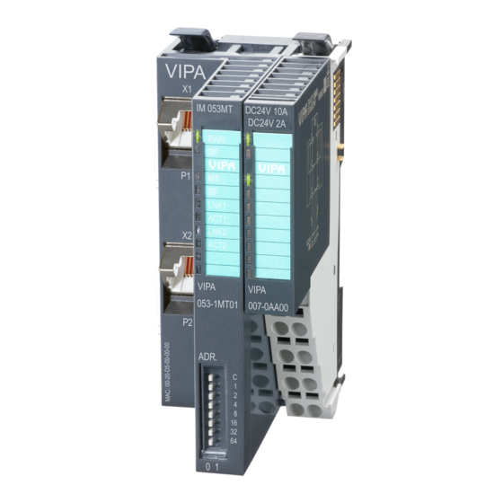
Manual VIPA System SLIO Chapter 2 Hardware description Structure Locking lever terminal module 053-1MT00 Labeling strip bus interface LED status indication bus interface Labeling strip power module LED status indication power module Backplane bus DC 24V power section supply Power module... - Page 34 Manual VIPA System SLIO Chapter 2 Hardware description For wires with a core cross-section of 0.08mm up to 1.5mm Terminal DC24V DC24V DC24V Pos. Function Type Description not connected DC 24V DC 24V for power section supply GND for power section supply...
-
Page 35: Technical Data
Manual VIPA System SLIO Chapter 2 Hardware description Technical Data Order number 053-1MT00 Type IM 053MT Module ID Technical data power supply Power supply (rated value) DC 24 V Power supply (permitted range) DC 20.4...28.8 V Reverse polarity protection Current consumption (no-load operation) - Page 36 Manual VIPA System SLIO Chapter 2 Hardware description HB300E - IM - RE_053-1MT00 - Rev. 11/28...
-
Page 37: Chapter 3 Deployment
Manual VIPA System SLIO Chapter 3 Deployment Chapter 3 Deployment This chapter describes the usage of the IM 053-1MT00 with ModbusTCP. Overview After a short introduction you may find here every information for the usage in the System SLIO. Content... -
Page 38: Basics
For the communication happens via TCP/IP, the slave system is referred to as server and a master as client. The Ethernet coupler from VIPA allows you to connect up to 64 modules of your System SLIO via Ethernet. Up to 8 clients may communicate simultaneously with the Ethernet coupler. - Page 39 Manual VIPA System SLIO Chapter 3 Deployment Layer 2 Layer 3 Layer 4 Layer 7 Telegram structure MAC/DLL 14 Byte 20 Byte 20 Byte Length depends on protocol While the Ethernet physics covers with its standard signal levels Layer 1, MAC/DLL MAC/DLL covers the conditions of the security layer (Layer 2).
- Page 40 Manual VIPA System SLIO Chapter 3 Deployment Layer 2 Layer 3 Layer 4 Layer 7 API structure MAC/DLL 14 Byte 20 Byte 20 Byte Length depends on protocol Port 502 ModbusTCP-Header Modbus User data ModbusTCP 6 Byte max.254 Byte ModbusTCP is a Modbus-RTU protocol, put upon TCP/IP.
-
Page 41: Accessing The System Slio
Manual VIPA System SLIO Chapter 3 Deployment Accessing the System SLIO In the following you will find the description of accessing the following Overview System SLIO areas via ModbusTCP. • I/O area • Parameter data • Diagnostics data Information concerning the allocation areas may be found in the description of the corresponding System SLIO module. - Page 42 0x and 1x gives you access to digital bit areas and 3x and 4x to analog word areas. For the Ethernet coupler from VIPA is not differentiating digital and analog data, the following assignment is valid: Bit area for master output...
- Page 43 Manual VIPA System SLIO Chapter 3 Deployment With the first start-up modules, which were parameterizable, operate with Accessing their default parameters. If you want to change parameters the Ethernet parameter data coupler respectively the corresponding modules may be parameterized via the integrated Web page.
-
Page 44: Access To The Ethernet Coupler
Manual VIPA System SLIO Chapter 3 Deployment Access to the Ethernet coupler The following illustration shows the Ethernet coupler access possibilities. Overview Web page System SLIO IM 053MT HTTP Web Server C-/Socket-Programming Port: 80 ModbusTCP Server Port: 502 Modbus-Utility VSCP... - Page 45 Manual VIPA System SLIO Chapter 3 Deployment The integrated HTTP web server is accessed by port 80. Web page The web page is built dynamically an depends on the number of modules, which are connected to the Ethernet coupler. Note! Please consider the System SLIO power and clamp modules do not have any module ID.
- Page 46 Manual VIPA System SLIO Chapter 3 Deployment Parameter If available the parameter data of the corresponding module may be shown and changed if necessary. Note! Only there is a configuration for a module, this may be used to check preset and current configuration.
- Page 47 Manual VIPA System SLIO Chapter 3 Deployment The ModbusTCP server is accessed via port 502. Via simple C programs it C-/Socket is possible to transfer data between PC and Ethernet coupler with programming ModbusTCP. For the deployment of the Ethernet couplers at a PC you should have a thorough knowledge in C programming, especially in socket programming.
- Page 48 ModbusTCP interface. For example, you may find the demo tool "ModbusScan32" from WinTech for download at www.win-tech.com. VSCP means VIPA Search and Control Protocol. This Windows software VSCP serves for the following functions:...
-
Page 49: Modbustcp
Manual VIPA System SLIO Chapter 3 Deployment ModbusTCP ModbusTCP is a Modbus protocol put upon TCP/IP, where the IP address General serves the addressing. ModbusTCP allows a client-server-communication, several clients may be provided from one server. The request telegrams sent by a master and the respond telegrams of the... -
Page 50: Modbus Function Codes
0x and 1x gives you access to digital bit areas and 3x and 4x to analog word areas. For the Ethernet coupler from VIPA is not differentiating digital and analog data, the following assignment is valid: Bit area for master output... - Page 51 Manual VIPA System SLIO Chapter 3 Deployment With the following Modbus function codes a Modbus master can access a Overview Modbus slave. The description always takes place from the point of view of the master: Code Command Description Read n bits...
- Page 52 Manual VIPA System SLIO Chapter 3 Deployment Code 01h: Read n bits of master output area 0x. Read n bits 01h, 02h Code 02h: Read n bits of master input area 1x. Command telegram ModbusTCP- Slave address Function code Address...
- Page 53 Manual VIPA System SLIO Chapter 3 Deployment Code 06h: Write 1 word to master output area 4x. Write 1 word Command telegram ModbusTCP- Slave Function Address Value Header address code word word x x 0 0 0 6 6byte 1byte...
- Page 54 Manual VIPA System SLIO Chapter 3 Deployment Code 16h: This function allows to mask a word in the master output area 4x. Mask a word Command telegram ModbusTCP- Slave Function Address Header address code word Mask Mask x x 0 0 0 8...
-
Page 55: Register Allocation
Manual VIPA System SLIO Chapter 3 Deployment Register allocation Address Access to I/O data 1x: 0001h ... 2000h Bit access to input area 3x: 0001h ... 0200h Word access to input area 0x: 0001h ... 2000h Bit access to output area 4x: 0001h ... -
Page 56: Led Status Indication
Manual VIPA System SLIO Chapter 3 Deployment LED status indication The LEDs installed to display the status allow extensive diagnostics during General the PowerON procedure as well as during operation. The result of the diagnosis is determined by the combination of the different LEDs and the current operating mode.
Need help?
Do you have a question about the IM 053MT and is the answer not in the manual?
Questions and answers