Table of Contents
Advertisement
Quick Links
Advertisement
Chapters
Table of Contents

Summary of Contents for OK Play Healthcare SprayClean
- Page 2 Warranty Obligations: OK Play Healthcare Pvt Ltd will, at its dole discretion, repair or replace, free of charge, part or parts there of as may be found, on examination, to have a manufacturing defect within the warranty period, subject to fulfilment of condition stipulated in terms and...
- Page 3 OK Play Healthcare Pvt Ltd. • In case OK Play Healthcare Pvt Ltd determines that defect in the product is due to inappropriate use of the product, but can be...
- Page 4 Exclusions of Warranty : The Warranty will become void due to the following : • Any physical damage due to accident or mis-handling. • Improper transportation, storage, installation, or handling. • Modification, alteration, disassembly, repair or replacement by unauthorized personnel. •...
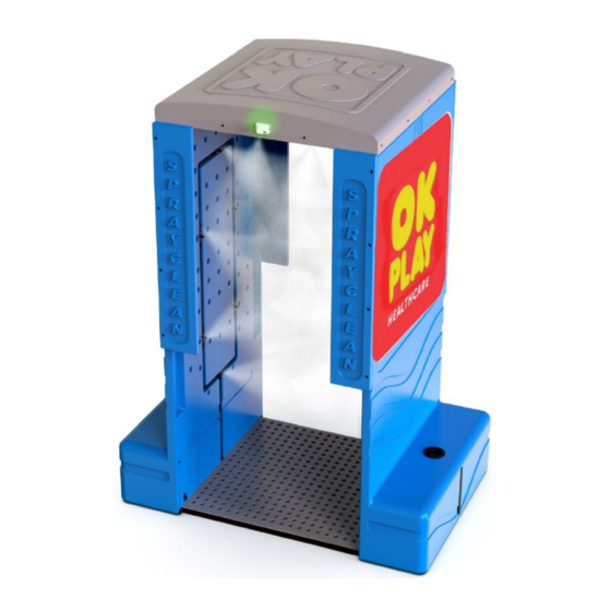
- Page 5 Installation and Operation Manual Model Name : “SprayClean” Model Number : OKPHC SC1A01...
- Page 6 • Do not drag any component which can lead to scratches or damage. Handle all the component carefully including electricals. • Inform OK Play Healthcare Pvt Ltd for any package damage or damage of any part(s) immediately before starting the assembly.
- Page 7 Unpacking in truction 1. The parts are wrapped in a cardboard box. 2. Do not use any hammer or knife or screwdriver to unpack the material. Use scissors to cut the packing material carefully as the process should not damage the electricals items inside. 3.
- Page 8 List of Components : Components Sketch / Picture Roof Roof Frame Angle Side Panel LH Side Panel RH...
- Page 9 Components Sketch / Picture Roof Frame Cross Link Front Panel (1 - 4) Tank Pipe Bottom Strips...
- Page 10 Components Sketch / Picture Beaker Toolbox Fasteners (PACK 1 - 9)
- Page 11 “SprayClean” Installation View Exploded view of the components...
- Page 12 Step - 1 : FRAME ASSEMBLY Objective: To assemble front panels to side panels & roof frame and to build a frame assembly (Step – 1.1 to Step – 1.22) Parts Required Remarks Tools Required Side Panel LH Part is labeled Allen Key 5mm Side Panel RH Part is labeled...
-
Page 13: Table Of Contents
Step – 1.2 Take out side-strip screws from the side panel LH (1) with the help of 5mm Allen key and discard the screws Step – 1.3 Take the fasteners from PACK-1 Fasteners: Fastener Details Bolt Position Allen Bolt M6 X 35 L 1,2,3,4 Plain Washer M6 1,2,34... - Page 14 Step – 1.4 Assemble the front panel (1) to side panel LH (1) and tighten using the fasteners from Pack-1 with the help of 4 mm Allen key...
-
Page 15: Step - 1.5
Step – 1.5 Assemble the front panel (1) to side panel LH (1) and tighten using fasteners from Pack-1 with the help of 4 mm Allen key... -
Page 16: Fasteners
Step – 1.6 Take the fasteners from PACK-2 Fasteners: Fastener Details Bolt Position Allen Bolt M6 X 35 L 1,2,3,4 Plain Washer M6 1,2,3,4 Step – 1.7 Assemble the front panel (2) to side panel LH (2) and tighten using fasteners from PACK-2 with the help of 5mm Allen key... - Page 18 Step – 1.8 Place the side panel RH horizontally Step – 1.9 Take out side-strip screws from the side panel RH (3) with the help of 5mm Allen key and discard the screws...
- Page 19 Step – 1.10 Take the fasteners from PACK-3 Fasteners: Fastener Details Bolt Position Allen Bolt M6 X 35 L 1,2,3,4 Plain Washer M6 1,2,3,4 Step – 1.11 Assemble the front panel (3) to side panel RH (3) and tighten using fasteners from pack-3 with the help of 5mm Allen key...
- Page 20 Step – 1.12 Take out side-strip screws from the side panel RH (4) with the help of 5mm Allen key and discard the screws...
- Page 21 Step – 1.13 Take the fasteners from PACK-4 Fasteners: Fastener Details Bolt Position Allen Bolt M6 X 35 L 1,2,3,4 Plain Washer M6 1,2,3,4 Step – 1.14 Assemble the front panel (4) to side panel RH (4) and tighten using the fasteners from Pack-4 with the help of 5mm Allen key...
- Page 23 Step – 1.15 Place assembled side panel RH and assembled side panel LH opposite to each other facing the nozzles and electric plug wiring side up (side position) Step – 1.16 Connect the roof frame angle (1) to assemble Electric Plug Wiring...
- Page 24 Step – 1.17 Take the fasteners from PACK-5 Fasteners: Fastener Details Bolt Position Allen Bolt M6 X 35 L 5,6,7,8 Hex. Nut M6 1,2,3,4 Allen Bolt M6 X 16 L 1,2,3,4 Plain Washer M6 Step – 1.18 Assemble the roof frame angle (1) on the both side panels RH &LH (side position) using the fasteners (for bolt positions 1 & 2) from PACK-5 with the help of 5mm Allen key and 10mm spanner...
- Page 25 Step – 1.19 Step – 1.20 Connect the roof frame angle (2) to assemble Assemble the roof frame angle (2) on both side panels RH & LH (side position) using the fasteners(for bolt positions 3 & 4) from PACK-5 with the help of 5mm Allen key and 10 mm spanner...
- Page 26 Step – 1.21 Assemble the roof frame cross link on the both side panels RH &LH (side position) using the fasteners (for bolt positions 5 to 8) from PACK-5 with the help of 5mm Allen key and 10 mm spanner...
- Page 27 Step – 1.22 Assemble the roof keeping the sensor upwards to the assembled roof frame and fasten using the fasteners from PACK-6 with the help of 4mm Allen key (side position) Fasteners from Pack - 6 : Fasteners Details Bolt Position CSK Allen Bolt M6 X 15 L Plain Washer M6 Hex.
- Page 28 Step - 2 : SENSOR ASSEMBLY Objective: To connect the sensor wire connectors to the connectors in the top electrical panel (side position) (step – 2.1 to step – 2.4) Parts Required Tools Required Frame assembly Screwdriver...
- Page 29 Step – 2.1 Open the Top electrical panel cover with the help of screwdriver SENSOR WIRING Step – 2.2 Take the sensor wiring to the top electric panel...
- Page 30 Step – 2.3 Push (connector -1) sensor wiring male connector to circuit female connector and (connector - 2) sensor wiring female connector to circuit male connector Connector - 1 Connector - 1 PUSH Connector - 2 Connector - 2 Step – 2.4 Close the top electrical panel with cover with the help of screwdriver...
- Page 31 Step - 3 : ROOF WATER PIPE CONNECTION Objective: To connect the roof water pipe with the connectors on assembled side panels LH & RH of the frame assembly to complete nozzle water circuit (side position) (Step – 3.1 to Step – 3.3) Parts Required Frame Assembly Tools Required...
- Page 32 Step – 3.1 Open the cover of roof water pipe carefully View A PULL THE COVER...
- Page 33 Step – 3.2 Push the roof water pipe to the elbow connection on the both sides (side panels LH & RH) Elbow – 1 : On side panel LH Elbow – 2 : On side panel RH...
- Page 34 LH ELBOW Push RH ELBOW PUSH...
- Page 35 Step – 3.3 Close the cover of roof water pipe Step – 4 : Bottom Strip Connection Objective: To connect the bottom strip to the side panels LH & RH of the frame assembly (side position) (step – 4.1 to step – 4.3) Parts Required Frame assembly Tools Required...
- Page 36 Step – 4.1 Take the bottom strip labeled (1) Step – 4.2 Assemble bottom strip (1) to the assembled side panel RH & LH using fasteners from PACK-8 with the help of 5mm Allen key Fasteners to be used (PACK-8) : Fastener Details Bolt Position Allen Bolt M6 X 16 L...
-
Page 38: Step - 5.1
Step - 5 : TILTING THE FRAME ASSEMBLY TO VERTICAL POSITION Objective: To hold the frame assembly carefully to tilt to vertical position (Step – 5.1) Parts Required Frame Assembly Step – 5.1 Hold the Frame assembly carefully and tilt to stand on vertical position... - Page 39 Step - 6 : COMPLETING FRAME ASSEMBLY Objective: To fasten roof bolts and bottom strips to complete frame assembly (vertical position) (Step – 6.1 to Step – 6.3) Parts Required Remarks Frame assembly Roof assembled Bottom strips Tools Required Allen key 4mm Spanner 10mm Step –...
-
Page 40: Take The Bottom Strip Labeled
Step – 6.2 Take the bottom strip labeled (2) -
Page 41: Step - 6.3
Step – 6.3 Assemble bottom strip (2) to the assembled side panel RH & LH using fasteners from PACK-9 with the help of 5mm Allen key Fasteners from PACK - 9 : Fastener Details Bolt Position Allen bolt M6 X 16 L LH &... - Page 42 Step - 7 : TANK PIPE CONNECTION & MAT ASSEMBLY Objective: To Connect tank pipe to the tank connectors at the side panel bottom frame and put the mat on the floor(vertical position) (Step – 7.1 to Step –7.3) Parts Required Completed frame assembly Tank pipe Step –...
- Page 43 Step – 7.2 Connect other end of the tank pipe (2) to the tank connector (side panel LH) PUSH...
- Page 44 Step – 7.3 Place the mats on the floor in between side panels RH & LH.
- Page 45 Step - 8 : WATER INLET ASSEMBLY Objective: To Fill the required disinfectant and clean water in the tank (Step-8.1 to Step – 8.6) Parts Required Completed frame assembly Beaker...
- Page 46 Step – 8.1 Open the cap of the tank Step – 8.2 Note the water requirement by looking at water level indicator of the tank.
- Page 47 Step – 8.3 Take the beaker and fill the required disinfectant Note : The calibrated beaker is provided for measuring the disinfectant solution to be added.
- Page 48 Step – 8.4 Pour the disinfectant into the tank. Step – 8.5 Fill the tank with clean water...
- Page 49 Step – 8.6 Close the cap of the tank...
- Page 50 Step - 9 : ELECTRICALS Objective: To Start “SprayClean” by switching on MCB inside the lower electrical panel and connecting to 230V electrical supply (Step – 9.1 to Step – 9.6) Parts Required Remarks Completed frame assembly Disinfectant &water filled...
- Page 51 Step – 9.1 Open the cover of the lower electrical panel (side panel LH) using 10 mm spanner...
- Page 52 Step – 9.2 Push the MCB switch up (inside lower electrical panel) PUSH Step – 9.3 Close the lower electrical panel with the cover using the spanner...
- Page 53 Step – 9.4 Demark the sensor zone and standing positions keeping in mind the social distancing Step – 9.5 Connect the plug to the 230V electrical connection PUSH...
- Page 54 Step – 9.6 Connect the switch to a 230V power supply to start the “SprayClean” PUSH...
Need help?
Do you have a question about the SprayClean and is the answer not in the manual?
Questions and answers