
Subscribe to Our Youtube Channel
Summary of Contents for Interscan Corporation HALIMETER PLUS
- Page 1 Interscan Corporation User Manual HALIMETER PLUS P .N. 120-0001 1 120-00011 Rev. New Halimeter PLUS User Manual 7/15/2020...
-
Page 2: Table Of Contents
Table of Contents Section 1 - Introduction ..............1 1.1 Precautions ............... 1 1.2 HALIMETER PLUS Packing Contents ....2 Section 2 – Instrument Description ..........3 2.1 Controls & Features ........... 3 Sample Inlet Tubing and Coupling Connector ... 5 Sample Straw ............ -
Page 3: Section 1 - Introduction
Section 1 - Introduction ® Congratulations on your purchase of the INTERSCAN Halimeter PLUS! The Halimeter PLUS is a complete reimagining of the world’s most trusted and widely used instrument for the analysis and treatment of chronic halitosis. Your instrument combines field-proven electrochemical sensing technology with an all- new electronics package, intuitive controls, and a real-time graphics display. -
Page 4: Halimeter Plus Packing Contents
WARNING: ALCOHOL OR CHLORINATED MOUTHWASH RESIDUE REMAINING IN THE MOUTH OF A SAMPLE SUBJECT WILL RESULT IN ERRONEOUS HALIMETER PLUS READINGS AND SERIOUSLY LIMIT SENSOR LIFE. IF MOUTHWASH HAS BEEN USED PRIOR TO TAKING A HALIMETER PLUS READING, RINSE OUT THE MOUTH THOROUGHLY WITH WATER AT LEAST 30 MINUTES PRIOR TO SAMPLING. -
Page 5: Section 2 - Instrument Description
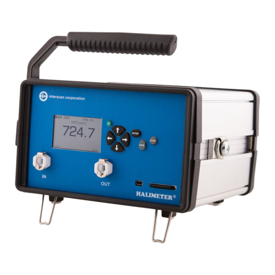
Section 2 – Instrument Description 2.1 CONTROLS & FEATURES Figure 1 below shows the Halimeter PLUS case and front panel features which are described in the table and sections that follow. CARRY HANDLE CONTROL KEYPAD LCD DISPLAY IN FITTING OUT FITTING SD CARD FIGURE 1... - Page 6 CARRY HANDLE – Enables easy carrying of the instrument between sampling locations. The handle can also be rotated 180° to the underside of instrument case for deeper angled tilt during table-top use as shown in Figure 2. To rotate handle, pull out on the handle mount on the left side of case and rotate handle towards the front of the instrument.
-
Page 7: Sample Inlet Tubing And Coupling Connector
2.1.2 CONTROL KEYPAD The Halimeter PLUS control keypad is detailed in Figure 4 below. Each button is described in the table that follows. ENTER BUTTON POWER BUTTON STOP BUTTON ARROW BUTTONS SAVE BUTTON FIGURE 4 POWER BUTTON – Press to turn power ENTER BUTTON –... -
Page 8: Sample Straw
To remove the tube adapter, press down on the metal locking tab on the top of the connector while pulling out on the tubing. The tube coupling connector fitted to the other end of the sample tubing shown below is provided as an interface for the sample straw. -
Page 9: Analog Output Connections
ANALOG OUTPUT CONNECTIONS The Halimeter PLUS is equipped with 0-2.5 V and 4-20 mA output signals available at the 10 pin rear panel terminal block as shown below. Each signal range corresponds to the full scale range of the instrument from 0 - max range. Connect to the terminal block by inserting wire conductor into the desired terminal and tightening the terminal’s screw. -
Page 10: Section 3 - Halimeter Plus Operation
Section 3 – Halimeter PLUS Operation 3.1 POWERING THE HALIMETER PLUS To turn the instrument on, press the green power button. The MAIN MENU screen showed on the right will be displayed. Check the battery life indicator in the lower right corner of the display and confirm that adequate battery life remains for use. -
Page 11: Measure Mode
The MAIN MENU offers 3 sub-menu selections that are detailed below: MEASURE – Sequential sub-menu of primary operating modes as follows: STARUP MODE > OFF MODE > ON MODE > SAMPLE MODE. See section 3.3 for details on the MEASURE sub-menu. SETUP –... - Page 12 during SENSOR STABILIZING mode. When the startup timer elapses, the instrument will automatically enter OFF MODE. OFF MODE In OFF MODE, the pump is turned off and the screen showed on the right will be displayed. This is the mode the Halimeter PLUS should be kept in when powered but not in use.
-
Page 13: Charging The Batteries
A graphical display of the continuous reading is also accessible during the breath sampling periods by pressing the RIGHT ARROW button. See section 5 for details on operating in SAMPLE MODE and taking samples. Any mode can be entered from the preceding mode by pressing the ENTER button or exited to the preceding mode by pressing the STOP button. -
Page 14: Setup Menu
indicator as shown on the right. The instrument can be charged with power on or off. For fastest charging of the Halimeter PLUS do not connect any other USB devices to the charger. NOTE: The internal batteries must have a charge to maintain the sensor bias voltage and minimize sensor warmup time. -
Page 15: Section 4 - Breath Sampling Considerations
Section 4 – Breath Sampling Considerations The Halimeter PLUS is designed to reliably measure VSC (Volatile Sulfur Compound) concentrations as part of a total program for the treatment of halitosis. Along with a thorough history and physical examination of the patient, the quantitative nature of ... -
Page 16: Sample Interferences
4.1 SAMPLE INTERFERENCES Part of ensuring accurate sample readings is minimizing sensor interferences that may result in false readings. One of the most common interferences to the Halimeter® PLUS sensor are vapors present in MOUTHWASH. The presence of residual mouthwash in the mouth will produce a false Halimeter®... - Page 17 3) When ready to collect sample, the end of the sample straw should be inserted into the patient’s mouth at a depth of approximately 1-2 inches (25-50mm) resting on the back of the tongue. The lips should be almost closed allowing for a slight gap between the lips and the sample straw.
-
Page 18: Section 5 - Taking Breath Samples
Section 5 – Taking Breath Samples After powering up the Halimeter PLUS, select MEASURE from the MAIN MENU by pressing the RIGHT ARROW button. This will open SENSOR STABILIZING MODE and a 5-minute timer will elapse. Upon the timer elapsing, the instrument will automatically enter OFF MODE. -
Page 19: Taking Samples
5.2 TAKING SAMPLES After zeroing the display, the instrument is ready for sampling. The following steps detail the sample procedure: 1) From ON MODE, press the ENTER button. This will advance the instrument to SAMPLE MODE starting a series of 3 sample cycles where 3 separate breath samples will be taken. -
Page 20: Auto Blockage Detection
5) This HOLD/SAMPLING cycle will repeat for 3 total samples. A new PEAK value will be added for each completed SAMPLE cycle above the timer field. At the end of the third SAMPLE cycle, the instrument will return to ON mode and the breath value display will show the average of the 3 PEAK sample values as indicated by “AVG”... -
Page 21: Section 6 - Data Storage And Access
Section 6 – Data Storage And Access Sample data can be stored on standard SD card media (a 32 GB card is provided with the instrument). Data is saved to the SD card automatically in ON mode and SAMPLE mode at a rate of one sample per second when AUTO SAVE is enabled (this is the default status on power up). -
Page 22: Accessing And Saving Data
Create file – Shown on the right. Use the RIGHT ARROW button to highlight the name field then use the UP/DOWN arrow buttons to change the character as desired and the RIGHT/LEFT arrow buttons to move the character position as desired. Press the SAVE button when finished to save the new file. - Page 23 until you hear a “click” and the card will eject. To re-insert, press the card all the way into the slot until you hear the “click”. The data files can be opened in Microsoft Excel or Notepad. Always save data files to a computer and perform any editing of the file to the saved version.
-
Page 24: Section 7 - Calibration
Section 7 - Calibration Periodic calibration of the Halimeter PLUS is required to compensate for decreased sensor sensitivity and maintain accuracy of readings. The frequency of calibration is a function of instrument use and the concentrations of volatile sulfur compounds (VSC) to which the sensor is exposed. - Page 25 1) Navigate to the MAIN MENU by pressing the STOP button successively until the MAIN MENU shown to the right is displayed. 2) Press the UP or DOWN ARROW buttons to move the cursor to highlight “Setup” then press the RIGHT ARROW button to enter the SETUP MENU.
- Page 26 When the value is correct, press the ENTER button to begin calibration sampling. 6) The screen shown on the right will now open showing the CAL timer (red arrow), the active ppb reading value and the peak ppb value. At this point, the breath subject should place the sample straw in his/her mouth and present a sample in the manner described in section 4.2.
-
Page 27: Section 8 - Sensor Replacement Procedure
Section 8 – Sensor Replacement Procedure The procedure detailed below addresses removing and replacing the Halimeter PLUS sensor. USE CARE WHEN WORKING INSIDE THE INSTRUMENT TO AVOID CONTACT WITH CIRCUIT BOARDS AND SURFACE MOUNT COMPONENTS! 8.1 SENSOR REMOVAL 1) Power the unit OFF. 2) Using your thumb and finger as shown in Figure 8-1, gently pry the right side of the rear bezel away from the side of the instrument case while pulling the bezel toward you. - Page 28 5) Remove the 4 screws from the corners of the rear panel as shown in Figure 8-6 below and set aside. Use care not to lose screws or plastic washers! Pull the panel away from the instrument case and set aside. FIGURE 8-6 FIGURE 8-6 6) The sensor is held in a manifold that is attached to the left side of the instrument case...
-
Page 29: Sensor Installation
8) Firmly grasping the sensor body as shown in Figure 8-10 below, slowly tilt the furthest edge of the sensor body away from the manifold and toward you as shown in Fig 8-10. Don’t attempt to pull the sensor straight out or rotate the sensor in the manifold. The senor should release from the manifold as shown in figure 8-11. - Page 30 2) Position the rear panel so the top and side edges are aligned with the instrument case as shown below in Figure 8-14. Secure with the panel screws. NOTE: screws should thread easily into the screw holes. If there is any significant resistance when threading the screws, STOP, back the screw out and re-align the panel holes with the threaded holes.
-
Page 31: Section 9 - Troubleshooting
Section 9 - Troubleshooting The chart below addresses common troubleshooting issues and provides probable causes and corrective actions to take. Always consult with the INTERSCAN service department for problems not on this list or if suggested corrective actions fail to address the problem. -
Page 32: Section 10 - Warranty
INTERSCAN CORPORATION’s sole obligation under this warranty is limited to repairing or replacing, at its option, any item covered under this warranty, when such item is returned intact, prepaid to the Factory (or designated service center). -
Page 33: Section 11 - Customer Service
Section 11 - Customer Service The INTERSCAN Customer Service Department can be reached at the numbers listed below: Toll-Free 800-458-6153 x121 818-882-2331 x121 818-341-0642 e-mail: service@gasdetection.com 11.1 RETURN AUTHORIZATION All units being returned for repair or service require a RETURN AUTHORIZATION NUMBER issued by the INTERSCAN Customer Service Department upon request.
Need help?
Do you have a question about the HALIMETER PLUS and is the answer not in the manual?
Questions and answers