
Related Manuals for GW Instek GDP-025 Series

Summary of Contents for GW Instek GDP-025 Series
- Page 1 Differential Probe GDP-025/050/100 Series USER MANUAL GW INSTEK PART NO. 82DP-10000MA1 ISO-9001 CERTIFIED MANUFACTURER...
- Page 2 This manual contains proprietary information, which is protected by copyright. All rights are reserved. No part of this manual may be photocopied, reproduced or translated to another language without prior written consent of Good Will Corporation. The information in this manual was correct at the time of printing. However, Good Will continues to improve its products and therefore reserves the right to change the specifications, equipment, and maintenance procedures at any time without notice.
-
Page 3: Table Of Contents
TABLE OF CONTENTS Table of Contents SAFETY INSTRUCTIONS ......4 Safety Symbols ................ 4 Safety Guidelines..............5 Power cord for the United Kingdom ........ -
Page 4: Safety Instructions
GDP Series User Manual AFETY INSTRUCTIONS This chapter contains important safety instructions that should be followed when operating and storing a differential probe. Read the following before any operation to ensure your safety and to keep the instrument in the best condition. Safety Symbols These safety symbols may appear in this manual or on the instrument. -
Page 5: Safety Guidelines
SAFETY INSTRUCTIONS Do not dispose electronic equipment as unsorted municipal waste. Please use a separate collection facility or contact the supplier from which this instrument was purchased. Safety Guidelines Do not use the probes in a damp environment or General where there is risk of explosion. - Page 6 GDP Series User Manual Make sure the maximum differential voltage Electrical Safety does not exceed 1400V (DC+AC peak) or 450 Vrms for the GDP-025 or 7000V (DC+AC peak) WARNING or 2200 Vrms for the GDP-050/GDP-100 Make sure the maximum voltage between each ...
- Page 7 SAFETY INSTRUCTIONS Location: Indoor Storage environment Relative Humidity: 10 to 90% Temperature: -30°C to 70°C Note: If the probe is not in use for more than 60 days, please store in a de-humidified environment to keep the probe dry. Location: Indoor ...
-
Page 8: Power Cord For The United Kingdom
GDP Series User Manual Power cord for the United Kingdom When using the instrument in the United Kingdom, make sure the power cord meets the following safety instructions. NOTE: This lead/appliance must only be wired by competent persons WARNING: THIS APPLIANCE MUST BE EARTHED IMPORTANT: The wires in this lead are coloured in accordance with the following code: Green/ Yellow:... -
Page 9: Getting Started
GETTING STARTED ETTING STARTED The Getting Started chapter introduces the probe’s features, appearance and functions. Main Features Model name Bandwidth Max differential voltage GDP-025 25MHz 450Vrms GDP-050 50MHz 6500Vrms GDP-100 100MHz 6500Vrms The GDP Series differential probes provide a Features safe means to measure differential voltages for all models of oscilloscopes. - Page 10 GDP Series User Manual black x1) Adapter (110V or 220V depending on region) Accessories BNC to BNC cable: 50Ω resistance, RG58C UL, GDP-050 100cm Banana plug to banana plug silicon wire, UL 20kV, 18AWG, Length 60cm. (red x1, black x1) HV IC clip, Max 6500V (DC+ACp-p) (red x1, ...
-
Page 11: Instrument Overview
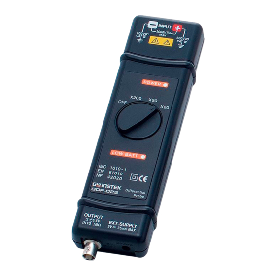
GETTING STARTED Instrument Overview GDP-025 Power supply Attenuation Intput terminals input function switch Over range indicator Power indicator Output GDP-050/ GDP-100 Attenuation Power supply Intput terminals function switch input Over range Power indicator Output indicator... - Page 12 GDP Series User Manual Category III input terminals. Input terminals The power indicator lights when the external Power Indicator power supply is connected. The over range indicator lights when the input Over range voltage exceeds rating. indicator External power supply input. 9V, 200mA. Power supply input Differential probe output.
-
Page 13: Measurement
MEASUREMENT EASUREMENT Risk of electric shock. The GDP Series differential voltage probes are designed for use with high High voltage voltages. When operating with high voltages ensure proper safety precautions are taken at all times. Please see the safety section for more details. Operation 1. - Page 14 GDP Series User Manual The power light must come on Caution Ensure the range light does not come on before measuring Deviation Table GDP-050 GDP-050 GDP-050 GDP-025 GDP-025 Model GDP-100 GDP-100 GDP-100 Attenuation X 1000 X 500 X 200 X 100 X 50 X 20...
- Page 15 MEASUREMENT Example With the probe set to a factor of X200, the oscilloscope set to a vertical deviation of 0.5V/div, the real vertical deviation is 200 x 0.5 = 100V/div. With a 50Ω load on the input of the oscilloscope the deviation becomes 200 V/div.
-
Page 16: Apendix
GDP Series User Manual PENDIX GDP Series Specifications GDP-025 Bandwidth DC-25MHz (-3dB)for x50, x200 DC-50MHz (for attenuation x20) Attenuation x20, x50, x200 Accuracy ± 2% ≤ 140Vp-p for x20 (≅ 45Vrms) Voltage Input ≤ 350Vp-p for x50 (≅ 110Vrms) Range (DC+AC ≤... - Page 17 APENDIX Electrical Safety to Dual Insulation IEC 1010-1 Installation Category III Degree of Pollution 2 Rated Voltage or Max Line-Earth: 600Vrms...
- Page 18 GDP Series User Manual GDP-050 Bandwidth DC-50MHz (-3dB)for x200, x500, x1000 DC-25MHz (for attenuation x100) Attenuation X100, x200, x500, x1000 Accuracy ± 2% ≤ 700Vp-p for x100 (≅230Vrms) Voltage Input ≤ 1400Vp-p for x200 (≅460Vrms) Range (DC+AC peak to peak) ≤...
- Page 19 APENDIX GDP-100 Bandwidth DC-100MHz (-3dB)for x200, x500, x1000 DC-50MHz (for attenuation x100) Attenuation X100, x200, x500, x1000 Accuracy ± 2% ≤ 700Vp-p for x100 (≅230Vrms) Voltage Input ≤ 1400Vp-p for x200 (≅460Vrms) Range (DC+AC peak to peak) ≤ 3500Vp-p for x500 (≅1140Vrms) ≤...
-
Page 20: Ec Declaration Of Conformity
GDP Series User Manual EC Declaration of Conformity GOOD WILL INSTRUMENT CO., LTD. No.7-1, Jhongsing Rd., Tucheng Dist., New Taipei City 236, Taiwan GOOD WILL INSTRUMENT (SUZHOU) CO., LTD. No. 69, Lushan Road, Suzhou New District Jiangsu, China declares that the below mentioned product GDP-025, GDP-050, GDP-100 Are herewith confirmed to comply with the requirements set out in the Council Directive on the Approximation of the Law of Member States... - Page 21 Current Probe and Power Supply USER MANUAL GW INSTEK PART NO. 82CP-425P0M01 ISO-9001 CERTIFIED MANUFACTURER...
- Page 22 November 2010 edition This manual contains proprietary information, which is protected by copyright. All rights are reserved. No part of this manual may be photocopied, reproduced or translated to another language without prior written consent of Good Will Corporation. The information in this manual was correct at the time of printing. However, Good Will continues to improve its products and therefore reserves the right to change the specifications, equipment, and maintenance procedures at any time without notice.
- Page 23 TABLE OF CONTENTS Table of Contents SAFETY INSTRUCTIONS ........5 Safety Symbols ............... 5 PRECAUTIONS ..........7 Preliminary Check ............... 7 OVERVIEW ............. 13 Current Proble Overview ........... 13 Features ................13 Names of Parts(Current Probe) ......... 14 ...
- Page 24 TABLE OF CONTENTS...
-
Page 25: Safety Instructions
SAFETY INSTRUCTIONS AFETY INSTRUCTIONS Safety Symbols This manual contains information and warnings essential for safe operation of the device and for maintaining it in safe operating condition. Before using the device, be sure to carefully read the following safety notes. symbol printed on the device indicates that the user should refer to a corresponding topic in the manual (marked with the... - Page 26 GCP Series User Manual The following symbols in this manual indicate the relative importance of cautions and warnings. Indicates that incorrect operation presents an DANGER extreme hazard that could result in serious injury or death to the user. Indicates that incorrect operation presents a WARNING significant hazard that could result in serious injury or death to the user.
-
Page 27: Precautions
PRECAUTIONS RECAUTIONS Follow these precautions to ensure safe operation and to obtain the full benefits of the various functions. Preliminary Check Before using the device the first time, verify that it operates normally to ensure that the no damage occurred during storage or shipping. If you find any damage, contact your dealer. - Page 28 GCP Series User Manual Un-insulated (core and shield case) Be careful to avoid damaging the insulation • surface while taking measurements. This instrument is made for use with the GCP- • 206P or GCP-425P POWER SUPPLY. It is possible to use a power supply other than the GCP-206P or GCP-425P, provided that the connector and pin assignments match, and that voltage and other electrical specifications are satisfied.
- Page 29 PRECAUTIONS 2. If basic insulation requirements cannot be met between the terminal to which this device is connected and other terminals of the measuring instrument, make sure that the voltage input to the measurement terminal does not exceed the safe voltage level (SELV- E). 3.
- Page 30 GCP Series User Manual Do not allow the device to get wet, and do not take • measurements with wet hands. This may cause an WARNING electric shock. To avoid electric shock when measuring live lines, • wear appropriate protective gear, such as insulated rubber gloves, boots and a safety helmet.
- Page 31 PRECAUTIONS The sensor head is a precision assembly including • a molded component, a ferrite core, and a Hall effect element. It may be damaged if subjected to sudden changes in ambient temperature, or mechanical strain or shock, and therefore great care should be exercised in handling it.
- Page 32 GCP Series User Manual Correct measurement may be impossible in the • NOTE presence of strong magnetic fields, such as near transformers and high-current conductors, or in the presence of strong electromagnetic fields such as near radio transmitters. When sending the device for repair, carefully to •...
-
Page 33: Overview
OVERVIEW VERVIEW Current Proble Overview This device can be directly connected to a BNC input connector of a waveform measuring instrument such as an oscilloscope or recorder, and by clamping on a conductor to be measured, allows the current waveform to be easily captured. Features Highly accurate current detection •... -
Page 34: Names Of Parts(Current Probe)
GCP Series User Manual Names of Parts(Current Probe) External view... -
Page 35: Parts Of The Sensor
OVERVIEW Parts of the Sensor Opening lever Operating lever for opening the sensor head. Always use this lever to open the sensor head. This clamps the conductor being measured, and Sensor head carries out the actual current measurement. It is a precision assembly including a molded component, a ferrite core, and a Hall effect element. - Page 36 GCP Series User Manual To avoid electric shock, do not touch the portion DANGER beyond the protective barrier during use. The output of this device is terminated • NOTE internally. Use a high-impedance input to the measuring instrument. With an input impedance of 50Ω, accurate measurement is not possible.
-
Page 37: Names Of Parts(Power Supply)
OVERVIEW Names of Parts(Power supply) Front view Power Power indicator indicator Power Power supply supply receptacles receptacles GCP-425P Rear View GCP-425P... - Page 38 GCP Series User Manual Front view GCP-206P Rear View GCP-206P...
- Page 39 OVERVIEW Power Supply Receptacle...
-
Page 40: Measure Procedure
GCP Series User Manual EASURE PROCEDURE Preparations for Measurement (Current Probe) 1. Have the GCP-206P or GCP-425P POWER Procedure SUPPLY, and oscilloscope or recorder for waveform measurement ready. Before turning on the power, make sure that the CAUTION voltage of the power supply being used matches the supply voltage indicated on the rear panel of the GCP-206P or GCP-425P The output of this device is terminated internally. - Page 41 OVERVIEW 4. Turn the GCP-206P or GCP-425P power switch...
-
Page 42: Demagnetizing And Zero Adjustment
GCP Series User Manual Demagnetizing and Zero Adjustment 1. With the waveform measurement instrument Procedure input at ground, adjust the trace to the zero position. 2. Set the input coupling of the waveform measurement instrument to DC. 3. Connect the output connector of the GCP-530 or GCP-1030 to the input connector of the waveform measurement instrument. - Page 43 OVERVIEW Do not demagnetize while the GCP-530 or GCP- • 1030 is clamping a conductor to be measured. Demagnetizing causes current to flow into the conductor, which may damage parts in the circuit to be measured. Check that the conductor being measured is not •...
-
Page 44: Measurement Procedure (Current Probe)
GCP Series User Manual Measurement Procedure (Current Probe) 1. Check that the system is safe, and that the Procedure preparations described in the preceding section have been carried out. 2. Pull the sensor opening lever, so that the sensor head opens. 3. - Page 45 OVERVIEW 5. It is now possible to monitor the current waveform. The output rate of the GCP-530 or GCP is 0.1 V/A. The current sensitivity can be derived from the voltage sensitivity of the waveform measurement instrument. For example, if the voltage sensitivity is 10mV/division, the current sensitivity is 100mA/division.
- Page 46 GCP Series User Manual The maximum continuous input range is based • on heat that is internally generated during CAUTION measurement. Never input current in excess of this level. Exceeding the rated level may result in damage to the probe. The maximum continuous input range varies •...
- Page 47 OVERVIEW Do not place any unclamped conductor with an • electric current of a frequency of 10 kHz or more near the sensor head. Current flowing in the conductor nearby may heat up the sensor head and cause its temperature to rise, leading to damage to the sensor.
- Page 48 GCP Series User Manual Depending on the measured current frequency, • however some sound may be produced by resonance, it has no effect on measurements. When performing continuous measurements, it is • necessary to be aware that the offset voltage drifts, depending on factors such as the ambient temperature.
- Page 49 OVERVIEW At high frequencies, common mode noise may • affect measurements taken on the high voltage side of circuits. If this occurs, reduce the frequency range of the waveform measuring instrument, or clamp onto the low voltage side of the circuit, as appropriate. Accurate measurement may be impossible in •...
-
Page 50: Preparations (Power Supply)
GCP Series User Manual Preparations (Power supply) 1. Turn the power switch off and connect the Procedure power cord. To ensure safety, connect the power cord to a properly grounded outlet. 2. Connect the power plug of the sensor to be used to the power receptacle of the GCP-206 or GCP- 425P. -
Page 51: Measurement Procedure (Power Supply)
OVERVIEW Measurement Procedure (Power supply) Make sure the sum of the current consumption of • NOTE the connected current probe(s) does not exceed the rated output current of the GCP-425P (See Fig.1) on page 25. When using the GCP-425P with Model GCP-530 or •... -
Page 52: Appendix
GCP Series User Manual PPENDIX The power supply fuse for the GCP-425P, and the power supply voltage selector, are housed in the power input socket on the rear panel. Fuse Replacement (for GCP-206P only) 1. Turn the power switch off, and then disconnect Procedure the power cord. - Page 53 APPENDIX 3. Remove the fuse on the fuse holder and replace with a new one of the same rating and specification. 4. Insert the fuse holder back into the power input socket to finish the replacement of fuse.
-
Page 54: Change The Power Supply Voltage Setting
GCP Series User Manual Change the power supply voltage setting 1. Repeat steps 1-2 in the “Fuse replacement” Procedure section on page 32. 2. Remove the voltage selector from the fuse holder, rotate it to the desired supply voltage value and then insert back into the fuse holder. The voltage vaule will appear in the voltage window. -
Page 55: Current Probe Specifications
APPENDIX Current Probe Specifications Accuracy is guaranteed at 23°C~+5°C (72°F±9°F) after the power has been on for 30 minutes. Model-specific specifications GCP-530 GCP-1030 Frequency range DC to 50 MHz (-3 dB) DC to 100 MHz (-3 dB) (Characteristics shown in Fig. (Characteristics shown in Fig. -
Page 56: Common Specifications (For Gcp-530 And Gcp-1030)
GCP Series User Manual Common specifications (for GCP-530 and GCP-1030) GCP-530 GCP-1030 0 to 40°C (32 to 104°F), 80 % RH or less (no Operating condensation) temperature and humidity range Rated Supply 12 V 0.5 V voltage Maximum Peak Non-continuous 50 Apeak Current Input Maximum 30 Arms (Derating according to frequency shown in Fig. - Page 57 APPENDIX External Sensor: dimensions Approx. 175(W)×18(H)×40(D)mm Approx. 6.89"(W)×0.71"(H)×1.58"(D)(excluding protrusions) Terminator: Approx. 55(W)×27(H) ×18(D) mm Approx. 2.17"(H) ×1.06"(W)×0.71"(D) Fig.3 Derating according to frequency (For GCP -530) 100k 100M Frequency [Hz] Fig.3 Derating according to frequency (For GCP -1030)
- Page 58 GCP Series User Manual Fig.4 Input impedance (For GCP-530) 100m 100k 100M Frequency [Hz] Fig.4 Input impedance (For GC P-1030)
-
Page 59: Power Supply Specifications
APPENDIX Power Supply Specifications Model-specific specifications Cable Lengths Sensor cable Approx. 1.5 m (59.0"), Power supply cable Approx. 1 m (39.4") GCP-425P GCP-206P Number of power supply connectors Rated output ±2.5 A (sum total of all 600 mA (sum total of all current channels) channels and all output... -
Page 60: Common Specifications (For Gcp-206P And Gcp-425P)
GCP Series User Manual Rated supply 50/60 Hz frequency Common specifications (for GCP-206P and GCP-425P) GCP-530, GCP-1030 Current Probe Compatible sensors Output voltage 12 V 0.5 V Temperature Within output voltage limits indicated above for ambient influence temperature in the range 0 to 40°C (32 to 104°F) Operating tempera- 0 to 40°C(32 to 104°F), 80%RH or less (no condensation) ture and humidity...
Need help?
Do you have a question about the GDP-025 Series and is the answer not in the manual?
Questions and answers