Table of Contents
Advertisement
Quick Links
Advertisement
Table of Contents

Related Manuals for NanoSense EP5000-Z

Summary of Contents for NanoSense EP5000-Z
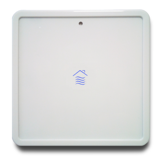
- Page 1 123 rue de Bellevue, 92100 Boulogne Billancourt France Tél : 33-(0) 1 41 41 00 02 - www.nano-sense.com EP5000-Z air quality probe Installation manual Date Modification / Update 16/12/2019 Initial Version www.nano-sense.com All Rights Reserved Tel : 33 (0)1 41 41 00 02...
- Page 2 Summary Security ................................3 Positioning ................................ 3 Flush mounting ..............................4 Wiring ................................4 Installation ................................ 4 Power on ................................4 Indication of LEDs in normal operation ......................5 Connections ..............................6 8.1. Power supply ..............................6 8.2. Remote control ..............................6 NFC ..................................
- Page 3 1. Security WARNING Danger of death, risk of electric shock and fire! The installation should only be undertaken by a qualified electrician! To apply for correct bus and power cables and to activate the device, comply with the state of the art and standards.
- Page 4 3. Flush mounting Use the backbox provided or an airtight insulated backbox with a waterproofing membrane through which the sheath passes. If the backbox passes through the sealing plane, seal between the backbox and the partition with a specific VOC free and silicone free sealant. Make sure that the backbox doesn’t contain Silicone.
- Page 5 not been powered recently, the LEDs may stay orange "breathing" for several minutes until the VOC sensor stabilizes. The start-up cycle includes built in tests and preheating of the VOC sensor and visual checks of LEDs The cycle lasts about 5 minutes in total. During this time no message is sent. LEDs indicate faults as follows: Sensor failure after startup Red Fixed followed by...
- Page 6 These thresholds can be adjustable by specific commands and the cognitive quality replaced by the quality of sleep for installation in a bedroom. 8. Connections Power supply 8.1. The power supply must be continuous (DC) and between 12 and 32V (24V nominal). Remote control 8.2.
Need help?
Do you have a question about the EP5000-Z and is the answer not in the manual?
Questions and answers