Table of Contents
Advertisement
Quick Links
Advertisement
Table of Contents

Summary of Contents for Clarus BALANCE
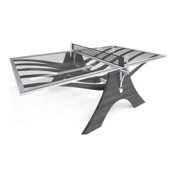
- Page 1 BALANCE Installation Instructions...
- Page 2 PROVIDED HARDWARE BT-A-SB-1 (10) (QUANTITY) BT-A-IG-1 (2) Net Assembly (1) Glass Top (1) BT-A-FR Assembly (1) BT-A-SO-1 (6) BT-A-OG-1 (2) BT-A-CR-1 (1) BT-W-SP-1 (10) 10. BT-W-SD-1 (2) 11. 3-8 16 x 3-8 Set Screw (20) 12. 1-4 20 x 1-2 bolt (10) 13.
- Page 3 ASSEMBLY • Tighten as last step of assembly, before laying glass on top of frame. STEP 1 • Assemble frame legs and arms together (Note order of BT-W-SP-1 parts). Fig. A Fig. A STEP 2 • Mount frame braces and glass frame. Fig.
- Page 4 STEP 3 • Attach table arms to table frame. Fig. C 3/8” – 16 x 3/16” 20x 1/4” – 20 x 3/4” 20x Fig. C STEP 4 • Attach table arms to center support bar. Fig. D 1/4” – 20 x 1/2” 20x Fig.
- Page 5 STEP 5 • Lower Clarus glass onto Balance table frame. Fig. E Fig. E STEP 6 • Mount net arms to each table leg. Fig. F 5/16” – 18 x 1” Set Screw 4x Fig. F STEP 7 • Feed cables through turnbuckles.
- Page 6 STEP 8 • Install net rods at end of net, feed cable through net rod and net. Fig. G Fig. G 32 x 3/16” 4x STEP 9 • Install turnbuckles, with ball end of cable, to set screws, leaving roughly 1/8” of threads exposed. Fig.
- Page 7 • Insert cable into turnbuckle and tighten set screw. STEP 13 • Tighten turnbuckles. STEP 14 • Center net on cables, tighten net rod set screws on one side, pull other side taught, and tighten net rod set screws. clarus.com | 888.813.7414 © 2018 Clarus. All rights reserved.
Need help?
Do you have a question about the BALANCE and is the answer not in the manual?
Questions and answers