Table of Contents
Advertisement
YG125-25 Maintenance Manual
With the ever increasing varieties of motorcycles, new structures and new techniques have increasingly been applied.
To help YINGANG TECHNOLOGY Co., Ltd users and maintenance personnel better understand the maintenance,
adjustment and repair techniques of YG125-25 motorcycle, we prepared this maintenance manual. This manual is expected
to facilitate the YINGANG TECHNOLOGY Co., Ltd users and maintenance personnel and provide technical guidance for
them.
The masterstroke of the manual is the YG125-25 motorcycle , and the contents in Chapter 1-Chapter 3 are applicable
to the adjustment of various parts of the motorcycle. Chapter 4-18 describes various constituting parts of the motorcycle
respectively. Chapter 19 contains the electrical system diagram.
The standard maintenance procedures, maintenance precautions and general maintenance knowledge are not
covered in this manual. Any user or maintenance personnel who needs the above information may refer to the related
materials
All materials, charts and various data, as well as performance indices referenced herein, are for the latest model in our
product family at the date this manual is printed. YINGANG TECHNOLOGY Co., Ltd. shall have the right to, at any time,
amend this manual without prior notice. The copyright of all parts of this manual belongs to China YINGANG
TECHNOLOGY Co., Ltd. and no units or individuals are allowed to reprint it the without consent of our company.
We hope you will enjoy the comfort and pleasure it brings to you during your driving!
Foreword
1
Foreword
Advertisement
Table of Contents

Related Manuals for Yingang YG125-25


Summary of Contents for Yingang YG125-25
- Page 1 All materials, charts and various data, as well as performance indices referenced herein, are for the latest model in our product family at the date this manual is printed. YINGANG TECHNOLOGY Co., Ltd. shall have the right to, at any time, amend this manual without prior notice.
-
Page 2: Table Of Contents
YG125-25 Maintenance Manual Contents Contents 1-15 Overview 16-22 Lubrication system 23-38 Inspection and adjustment 39-43 Fuel system 44-48 Removal and installation of engine 49-63 Cylinder head, cylinder and piston 64-75 Clutch and Right crankcase cover 76-84 Magneto and starting system... -
Page 3: Overview
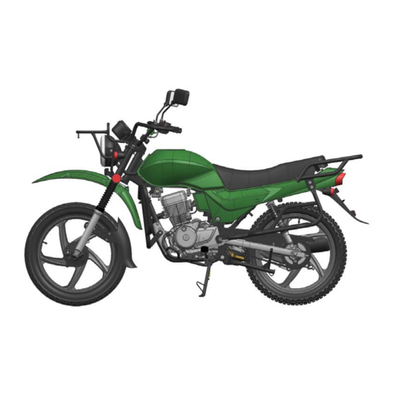
YG125-25 Maintenance Manual Overview 1、Overview Engine Number Position Bar Tool About Motorcycle Maintenance Maintenance Period Table Technical Data of Main Performance Symbol Descriptions Standard Torque Values Engine Number Position Photo of Complete Vehicle: Frame Number Position: Engine Number Position: Engine Number... - Page 4 YG125-25 Maintenance Manual Overview Maintenance Precautions Whenever reassembling after being disassembled, To disassemble and assemble a motorcycle, replace new washers, sealing members, etc. special service tools (SST) and general-purpose tools must be used in accordance with relevant regulations. While fastening bolts or nuts, proceed in diagonal crossing sequence to gradually screw down to the required torque for 2 to 3 tries.
- Page 5 YG125-25 Maintenance Manual Overview are not too long or are falling off. The connector shall be fully inserted in place. For a connector with lock, confirm whether the lock is completely fixed. Make sure the harness is not falling off...
- Page 6 YG125-25 Maintenance Manual Overview 13. specified position on the frame. The wire harness shall not be slackened or be forcibly pulled. 14. The clamp shall reliably bite the wire harness If the wire harness has to contact the edge or sharp corner parts, the contacting part shall be protected with hose or adhesive tape.
- Page 7 YG125-25 Maintenance Manual Overview 15. When wiring, note when turning it leftwards or 19. Do not forcibly twist or forcefully bend the cable. rightwards to the limit position, the wire harness Because a deformed or damaged cable is the shall not be tightened up or slackened, and make cause of bad operation and damage.
- Page 8 YG125-25 Maintenance Manual Overview Technical Data of Main Performance Item Data Length 2120mm Width 870mm Height 1070mm Wheelbase 1315mm Min. ground clearance 200mm Complete vehicle weight Non-loaded weight: 138kg, Curb weight: 213kg, Frame type Cradle type Rake angle 28° Front suspension device spring &...
- Page 9 YG125-25 Maintenance Manual Overview Mode Single-cylinder force air –cooling 4-stroke engine Cylinder bore × Stroke 56.5mm×49.5mm Cylinder displacement 125cc Compression ratio 8.8:1 Max. power 7.5kw/9000rpm Max. torque 8.6N.m/7500rpm Valve clearance (cold) IN: 0.06-0.08 EX: 0.06-0.08 Valve driving gear Chain drive...
- Page 10 YG125-25 Maintenance Manual Overview Electric generator permanent magnet DC magneto Accumulator capacity 12V7Ah Power supply system DC power supply, and the electric generator is only used to recharge the accumulator Fusible cutout 15A/10A Spark plug D8RTC Spark plug gap 0.7-0.9mm...
- Page 11 YG125-25 Maintenance Manual Overview Vehicle body Thread diameter Item Quantity Torque value (N.m Thread locker (mm) Front wheel spindle 50~60 Front vibration damper plate 30~40 Real wheel spindle nut 60~90 Rear fork shaft nut 50~60 30~40 Engine hanging bolt 20~30 Steering handle set bolt 20~30...
- Page 12 YG125-25 Maintenance Manual Overview Bar Tool Motorized gun: special power tool for mantling/ Pawl socket: for mantling/dismantling oil filtering element dismantling bolt and nut nut and clutch nut A and B bolt socket: for mantling/dismantling A and B Socket: for mantling/dismantling nuts and bolts...
- Page 13 YG125-25 Maintenance Manual Overview Dial gauge: to measure the wheel bouncing, cylinder Cylinder barometer: to measure the cylinder pressure inner diameter, etc. Wrench: measure tighteness of ad bolt Vernia caliper: measure size of rear wheel hub internal diameter Tire barometer: to measure the tire pressure...
- Page 14 C: Cleaning. R: Replacement. A: Adjustment. L: Lubrication. * This item is subject to maintenance by persons from YINGANG TECNOLOGY Service Station. If the user has special service tools, maintenance accessories or maintenance ability, it can repair it by itself.
- Page 15 YG125-25 Maintenance Manual Overview Each time reassembled after being removed and disassembled, it must be replaced with a new one. Explanation Measures to be prompted during operating, inspecting and maintaining. NOTICE: Special instructions or disposal measures given to prevent motorcycle from being damaged.
-
Page 16: Lubrication System
Lubrication system YG125-25 Maintenance Manual 2、Lubrication system Maintenance notice Inspection of lubricating oil Troubleshooting Replacement of lubricating oil Lubricating Position of Complete Vehicle Cleaning of Lubricating Oil Strainer Lubrication of Control Lines Cleaning and Replacement of Lubricating Oil Filter Engine Lubrication System Diagram... - Page 17 Lubrication system YG125-25 Maintenance Manual ● ● Troubleshooting Lubricating oil contaminated Lubricating oil consumes too fast 1. Fail to replace lubricating oil according to the There is leakage with the engine; maintenance period table; The piston ring is worn. 2. The pouring orifice thread is damaged thus causing The inlet/exhaust valve guide is worn;...
- Page 18 Lubrication system YG125-25 Maintenance Manual Engine Lubrication System Diagram Camshaft oil through Cylinder head oil through Crankshaft oil through Cylinder oil through Oil filter Spindle oil through Oil pump Oil strainer Countershaft oil through...
- Page 19 Lubrication system YG125-25 Maintenance Manual Cylinder block, cylinder head, camshaft bearing seat and a Left crankcase body oil through camshaft oil through Replacement of lubricating oil While replacing lubricating oil, it shall be carried out before the engine has cooled down. This will ensure quick and complete discharge of the engine oil inside the crankcase.
- Page 20 Lubrication system YG125-25 Maintenance Manual CAUTION Application of engine oil of poor quality will have an impact on the functional performance and life span of the motorcycle engine. Cleaning of Lubricating Oil Strainer It shall be carried out while replacing lubricating oil.
- Page 21 Lubrication system YG125-25 Maintenance Manual Notice Before the crankcase is refilled with fresh engine oil, the engine oil filter must be cleaned. Oil Pump In case of failure, the oil pump needs to be removed for repair or replacement. This section includes the following contents: Steps and illustration for oil pump removal;...
- Page 22 Lubrication system YG125-25 Maintenance Manual Steps for oil pump installation: The installation procedures are the removal procedures in reverse order. Pay attention to the following points during the installation: 1、 The spare parts shall be clean and intact; 2、 Install clutch assembly, and the retaining nut M18 shall be coated with thread retaining adhesive LOCTITE243;...
-
Page 23: Inspection And Adjustment
Inspection and adjustment YG125-25 Maintenance Manual 3、Inspection and adjustment Maintenance notice Brake system Spark plug Running system Lubricating oil Clutch control line Oil output tank Driving chain Timing phase Battery Checking Cylinder pressure Replacement of Fuse Timing chain tension Brake lamp adjustment... - Page 24 Inspection and adjustment YG125-25 Maintenance Manual yellow line will be revealed at the crack point. Explanation: Unless expressly stated or indicated in the maintenance period table, check and adjust all parts of the YG125-30A motorcycle according to the contents hereof before using it.
- Page 25 Inspection and adjustment YG125-25 Maintenance Manual Spark Plug Remove the spark plug cap. Remove the spark plug with Lubricating oil a socket wrench. Visually check whether there is any Park the motorcycle on a flat surface, let the engine stop...
- Page 26 Inspection and adjustment YG125-25 Maintenance Manual Timing phase While aligning It shall be carried out when the vehicle is new or there is any question about the timing phase. Remove the cylinder head cover Turn the crankshaft pulley Counterclockwise to align the scale line “I”...
- Page 27 Inspection and adjustment YG125-25 Maintenance Manual position. sealing washer and detach the old chain tensioner. Take The main reasons for insufficient cylinder pressure care not let the sealing washer and so on fall into the include: crankcase. Insert the tensioner 4 locking key...
- Page 28 Inspection and adjustment YG125-25 Maintenance Manual Valve clearance the top of the crankcase cover, and both intake and exhaust rock arms do not move but stop at their loosest Notice: position, which shows that the piston is in its top dead While adjusting the valve clearance, the engine shall center position of the compressing stroke.
- Page 29 Inspection and adjustment YG125-25 Maintenance Manual Idle speed Notice Air filter Cleaning and replacement of air filter Check and adjust the idle speed after all other items Remove the left side covers Handle it carefully to of the engine have been adjusted to the specified avoid scraping.
- Page 30 Inspection and adjustment YG125-25 Maintenance Manual Coarse adjustment: If the fine adjustment is not satisfying, separate the throttle control line with throttle valve body and unscrew the retaining nut B to make adjust the free stroke in a larger range. Screw up the retaining but B after the adjustment.
- Page 31 Inspection and adjustment YG125-25 Maintenance Manual I If the brake fluid in both the front cylinders is drained, bleed air from the deflating valve of the brake caliper with a vacuum pump, and then refill brake fluid into the Actuate the front brake handle cylinder.
- Page 32 Inspection and adjustment YG125-25 Maintenance Manual (1)Pulling the rear brake, checking the wear and tear of Operating brake, if the wears limit line of the brake shoe touch to the side of the brake disc. It shows that the brake the brake shoe.
- Page 33 Inspection and adjustment YG125-25 Maintenance Manual Clutch control line specs Front tire Rear tire Clutch is the key part of transmitting power in motorcycle 3.0-18 3.25-18 transmission system,should adjust it according to the Cold tire air Front tire Front tire pressure following overhauling content.The content is the free...
- Page 34 Inspection and adjustment YG125-25 Maintenance Manual turn the clutch operating arm by a proper angle and remount it, and then mount the clutch control line, finally If the chain is too loose or too tight, make adjustment. adjust it to a satisfied free stroke according to the fine Adjusting methods: adjustment.
- Page 35 Inspection and adjustment YG125-25 Maintenance Manual Cleaning and coating oil supply. Seriously corroded conductor connectors of the battery shall be replaced. Notice This model uses the oil seal chain, so the selected washing oil shall be in corrosive to the oil seal; while...
- Page 36 Inspection and adjustment YG125-25 Maintenance Manual Replacement of Fuse cause serious hurt to skin and eyes by contact. In case of contact with it, wash it off for 5 Set the ignition switch to “OFF” position. The specified minutes and see a doctor immediately.
- Page 37 Inspection and adjustment YG125-25 Maintenance Manual Loose the screw to disassemble the headlight. Rotating , directly unplugging Rotating and disassemble the bulb. Install the new bulb in reverse order Headlight bulb 12V55W Front and rear lamp bulb ...
- Page 38 Inspection and adjustment YG125-25 Maintenance Manual fork bracket for several times, and check the front per the maintenance period table. And check all the cotter suspension for normal operation. pins, safety gripping gears, locks, etc. If abnormal noise or “Crack” sound is heard, check all the fasteners and screw them up to the specified torques.
- Page 39 YG125-25 Maintenance Manual Fuel system 4、Fuel system Fuel tank Throttle valve body Air filter...
-
Page 40: Fuel System
YG125-25 Maintenance Manual Fuel system Fuel system Maintenance notice Disassembly and assembly of fuel tank Troubleshooting Removal and installation of air filter Removal and installation of fuel tank Removal and installation of carburetor Maintenance notice This section introduces the knowledge related to the fuel system. - Page 41 YG125-25 Maintenance Manual Fuel system Removal and installation of fuel tank Disassemble step Remove the seat Installation steps Unscrew one connecting bolts The installation procedures are the removal procedures in Unscrew reverse order. While installing, note that the wiring of the fuel pump control wire shall be in strict accordance with the wiring diagram.
- Page 42 YG125-25 Maintenance Manual Fuel system Remove and installation of throttle body Installation steps: Disassemble step: The installation procedures are the removal procedures in reverse order. While installing, the locating slot must be Removal of rear wheel aligned with the locating lobe of throttle body Warning: Do not further disassemble the removed throttle body;...
- Page 43 YG125-25 Maintenance Manual Fuel system Aintenance of Air Cleaner Component Damage form Trouble symptom of motorcycle Repair method description The engine is difficult to start.Insufficient engine output;Poor performance of engine C1ean the filtering Too much dust deposit during idle run.Excessive fuel element.c1ean...
- Page 44 YG125-25 Maintenance Manual Removal and installation of engine 5、Removal and installation of engine...
-
Page 45: Removal And Installation Of Engine
YG125-25 Maintenance Manual Removal and installation of engine Removal and installation of engine Maintenance notice Installation of engine Removal of engine Maintenance notice It is only necessary to remove the engine from the frame when performing maintenance on the engine’s crankshaft, balancing shaft, driving parts, etc. - Page 46 YG125-25 Maintenance Manual Removal and installation of engine Park the motorcycle on the plane ground, and Detach the earth wire from the negative pole of the completely drain the engine lubricating oil. battery. Screw plug for oil draining Remove clutch cable...
- Page 47 YG125-25 Maintenance Manual Removal and installation of engine Remove the drive chain 11. Remove the gear shift pedal and left rear cover. 12. To remove the rear brake pedal Remove the rear absorber and rear fork connecting bolt;...
- Page 48 YG125-25 Maintenance Manual Removal and installation of engine During installation, note that the wiring of cable shall be in strict accordance with the wiring diagram. Remove the 4 engine bracket and the frame connecting bolt Remove the 2 front suspension bolt...
- Page 49 YG125-25 Maintenance Manual Cylinder Head, Cylinder and Piston 6、Cylinder head, cylinder and piston Cylinder head cover Cylinder head Cylinder...
-
Page 50: Cylinder Head, Cylinder And Piston
YG125-25 Maintenance Manual Cylinder Head, Cylinder and Piston Cylinder head, cylinder and piston Maintenance notice Cylinder head Troubleshooting Cylinder Cylinder head cover Piston Camshaft Maintenance notice The lubrication of the camshaft and rocker arm is implemented by pumping oil by the oil pump through the oil troughs of the cylinder, cylinder head and cylinder head cover;... - Page 51 YG125-25 Maintenance Manual Cylinder Head, Cylinder and Piston Roundness 0.003 Cylindricity 0.004 Top planeness 0.05 φ52.37~φ52.39mm mm φ52.37mm Piston external diameter Fit clearance with 0.01mm~0.04mm 0.04mm cylinder Piston and piston φ12.995mm~φ13mm φ12.995mm Piston pin external diameter φ13.002mm~φ13.008mm φ13.008mm Piston pin hole...
- Page 52 YG125-25 Maintenance Manual Cylinder Head, Cylinder and Piston Troubleshooting Low cylinder pressure Piston or cylinder wall scratched or scuffed. ● Excessive noise Valve: Incorrect valve clearance adjusted; Incorrect valve adjustment; Valve ablated or bent; Valve jammed or valve spring broken;...
- Page 53 YG125-25 Maintenance Manual Cylinder Head, Cylinder and Piston Cylinder head cover To remove the cylinder head cover: Remove the lower / upper eyehole covers and turn the crankshaft so that the piston is at the upper dead point of the compression stroke.
- Page 54 YG125-25 Maintenance Manual Cylinder Head, Cylinder and Piston Camshaft Strip the timing chain from the timing driven sprocket, To remove the camshaft: and remove the timing driven sprocket. Remove the lower / upper eyehole cover and turn Remove the camshaft the crankshaft so that the piston is at the upper dead point of the compression stroke.
- Page 55 YG125-25 Maintenance Manual Cylinder Head, Cylinder and Piston Max. lift measurement Outside micrometer After properly timing, pull off the tensioner locking Cylinder head key and coat the mixture of engine oil and To remove the cylinder head: molybdenum disulfide on the tensioner to make it Remove the muffler exhaust pipe tensioned;...
- Page 56 YG125-25 Maintenance Manual Cylinder Head, Cylinder and Piston Pull off the spark plug cap, To mount the cylinder head: Installation is in the reverse order of removal. Precautions for installation: Confirm the location pin; clean all parts and components, and check whether the cylinder head oil through is unobstructed, clean and free of leak.
- Page 57 YG125-25 Maintenance Manual Cylinder Head, Cylinder and Piston Disassemble and assemble the cylinder head according to the following diagram. Use the valve remover / replacer to remove and mount the intake valve and exhaust valve. The spark plug must be tightened to the specified tightening torque of 15~20N.m for fear of leak.
- Page 58 YG125-25 Maintenance Manual Cylinder Head, Cylinder and Piston Muffler double head bolts Gas CAM shaft baffle Bolt M6*16 rectangular seals EX ≥φ5.15mm Cylinder head inspection Check whether the cylinder head is unobstructed, clean and free of leaks; check the cylinder head’s spark plug Outside micrometer hole and valve seat for cracks;...
- Page 59 YG125-25 Maintenance Manual Cylinder Head, Cylinder and Piston Remove cylinder connecting bolt Remove the tensioner Remove the cylinder; remove the cylinder gasket. Chain slide Notice: Do not drop the location pin into the crankcase. Do not bruise the cylinder wall.
- Page 60 YG125-25 Maintenance Manual Cylinder Head, Cylinder and Piston Check the cylinder wall for deformation, and use the edge out the piston pin. ruler and clearance gauge to inspect the planeness of the Take out the piston. cylinder’s joining surface. Piston pin retainer Piston Maintenance limit: ≤0.05mm.
- Page 61 YG125-25 Maintenance Manual Cylinder Head, Cylinder and Piston Do not drop the piston pin retainer into the crankcase. corrugated ring joint staggering with both lip rings by 90 °, and with the two lip rings staggering with each Disassembly and assembly of piston: Disassemble and assemble piston according to the other by 180°...
- Page 62 YG125-25 Maintenance Manual Cylinder Head, Cylinder and Piston Piston Piston ring Piston pin Piston pin circlip ≤0.65mm, Second spring ≤0.7mm. Piston inspection Check the piston for abrasion or damage, cracks, etc. and check the skirt section for scratch. Measure the piston external diameter at the position 10mm above the piston skirt.
- Page 63 YG125-25 Maintenance Manual Clutch and Right crankcase cover 7、Clutch and Right crankcase cover Clutch Engine Right crankcase cove...
-
Page 64: Clutch And Right Crankcase Cover
YG125-25 Maintenance Manual Clutch and Right crankcase cover Clutch and Right crankcase cover Maintenance notice Clutch Troubleshooting Right crankcase cover Maintenance notice To carry out the maintenance stated herein, it is unnecessary to detach the engine from the frame. However, the engine lubricating oil must be discharged. - Page 65 YG125-25 Maintenance Manual Clutch and Right crankcase cover Troubleshooting Clutch In case of clutch operation failure, a better correction may usually achieved by adjusting the clutch handle free stroke. Clutch slipping while accelerating Insufficient free stroke; Clutch disc abrasion;...
- Page 66 YG125-25 Maintenance Manual Clutch and Right crankcase cover Right crankcase cover To remove the cylinder head cover: Remove the oil drain plug to drain the engine oil inside the crankcase. To install the right crankcase cover: Confirm the location pin; clean up the residual sealing paper gaskets on the right crankcase and right crankcase cover.
- Page 67 YG125-25 Maintenance Manual Clutch and Right crankcase cover Adjust the direction of the clutch operating lever, Mount the clutch operating lever, rear brake return spring, cotter pin, rear brake lamp switch, etc. Refill engine oil. Notice: Do not scrape the crankshaft oil seal.
- Page 68 YG125-25 Maintenance Manual Clutch and Right crankcase cover Disassemble and assemble of right crankcase cover Procedure Quantity Remarks Removing order Installation is in the reverse order of removal Right crankcase cover Right crankcase cover sealing paper gasket Replace it with a new one while assembling...
- Page 69 YG125-25 Maintenance Manual Clutch and Right crankcase cover Remove the right crankcase cover (See “Removal of facing the main shaft right bearing. right crankcase cover"). Mount the clutch. Clutch Washer Remove the clutch push rod with the clutch push rod...
- Page 70 YG125-25 Maintenance Manual Clutch and Right crankcase cover Assemble the right crankcase cover by turning the clutch push rod until its rack side faces the crankshaft. (See “Installation of right crankcase cover"). Right crankcase cover Warning Thread retaining adhesive LOCTITE243 must be...
- Page 71 YG125-25 Maintenance Manual Clutch and Right crankcase cover Removal / Installation of Clutch Procedure Quantity Remarks Removing order Installation is in the reverse order of removal Tightening torque 12N.m. clutch bush clutch assembly Nut M14*1 Flat washer Deep groove ball...
- Page 72 While assembling, the clutch disc must be coated with lubricating oil; in case of replacing new clutch disc, it must be soaked in oil for over 24 hours before being assembled. Do not further disassemble the clutch housing, otherwise damage will occur. Explanation: While unscrewing bolt, do it in a crossing way twice or thrice.
- Page 73 Measure the free length of the clutch spring. Maintenance limit: ≥41.3mm. Clutch inspection Check whether the housing splice has scars or cuts Clutch spring free length measurement due to the collision of clutch disc. Inspection Vernier calipers Are there scars or cuts? Check the clutch disc.
- Page 74 YG125-25 Maintenance Manual Magneto and starting system 8、Magneto and starting system Idle gear Double-linked gear cover Left front cover Rotor assembly Double-linked Gear Disk gear Engine...
-
Page 75: Magneto And Starting System
YG125-25 Maintenance Manual Magneto and starting system Magneto and starting system Maintenance notice Rotor assembly Left front cover Starting motor and starting transmission system Maintenance notice To carry out the maintenance stated herein, and the engine lubricating oil must be drained.。... - Page 76 YG125-25 Maintenance Manual Magneto and starting system Left front cover To remove the left front cover: Remove the gear shift pedal and left rear cover, and separate the magneto lead connector with the main cable. Gear shift pedal Left rear plate...
- Page 77 YG125-25 Maintenance Manual Magneto and starting system Disassembly and assembly of left front cover Disassemble and assemble the left front cover according to the following diagram. Use the thread retaining adhesive LOCTITE 648 while assembling the pressure plate bolt. Use the thread retaining adhesive LOCTITE 648 while assembling the magneto stator connecting bolt.
- Page 78 YG125-25 Maintenance Manual Magneto and starting system Rotor assembly To remove the clutch: Remove the left front cover (See Removal of left Disk gear Disk gear washer front cover). Remove the starting idle gear, double-linked gear, Double-linked Gear Notice: Do not let the semicircular key drop into the crankcase.
- Page 79 YG125-25 Maintenance Manual Magneto and starting system Disassembly and assembly of rotor assembly Disassemble and assemble the rotor assembly according to the following diagram. Use thread retaining adhesive LOCTITE 648 on the screw while assembling, with the tightening torque being 10-14N.m...
- Page 80 YG125-25 Maintenance Manual Magneto and starting system Remove the starting motor connecting bolt M6×25. and screw up the nut M12 to the torque of 45N.m Push the motor towards the right and lift it, and then carefully take it out from the left side.
- Page 81 YG125-25 Maintenance Manual Magneto and starting system teeth, etc. To install the double-linked gear cove: 3、Check the idle gear shaft and double-linked gear shaft ⑴Clean up the left front cover and parts,mount the for bending. starting idle gear, double-linked gear, etc.
- Page 82 YG125-25 Maintenance Manual Crankcase, crankshaft and Shift mechanism 9、Crankcase, crankshaft and Shift mechanism Right hand crankcase body Gearshift drum Crankshaft Main shaft Counter shaft Left hand crankcase body...
-
Page 83: Crankcase, Crankshaft And Shift Mechanism
YG125-25 Maintenance Manual Crankcase, crankshaft and Shift mechanism Crankcase, crankshaft and Shift mechanism Maintenance notice Crankshaft and balance shaft Troubleshooting Variable transmission system Crankcase Maintenance notice To carry out the maintenance stated herein, the engine must be removed from the frame. - Page 84 YG125-25 Maintenance Manual Crankcase, crankshaft and Shift mechanism Troubleshooting Noise from engine Crankshaft bearing worn; Connecting rod big end bearing worn; Driving/driven shaft bearings worn; Balance shaft supplementary tooth spring failure. Driving/driven shaft gears engaged badly Shift fork bent or damaged;...
- Page 85 YG125-25 Maintenance Manual Crankcase, crankshaft and Shift mechanism Crankcase Notice To remove the crankcase: Do not pry the left/right hand crankcase body by Remove the engine from the frame (engine oil fully inserting such tools as screwdrivers into the mould drained) and put it on the assembly operating table.
- Page 86 YG125-25 Maintenance Manual Crankcase, crankshaft and Shift mechanism Mount the mould closing bolt and fasten it. Mount other parts and components of engine, mainly include right hand crankcase cover, clutch, gear shifter, cylinder head cover, camshaft, cylinder head, cylinder, piston, left front cover, rotor assembly, electrical starting transmission system, driving drive sprocket, etc.
- Page 87 YG125-25 Maintenance Manual Crankcase, crankshaft and Shift mechanism Removal and installation of crankcase Procedure Quantity Remarks Removing order Installation is in the reverse order of removal Right hand crankcase O-ring engine oil filter net Release oil bolt Left hand crankcase...
- Page 88 YG125-25 Maintenance Manual Crankcase, crankshaft and Shift mechanism Disassemble and assemble the left hand crankcase according to the following diagram. Do not remove breather pipe joint, otherwise damage will be caused. Generally, do not remove the bearing; if it is removed, coat engine oil on surfaces of spare parts while pressing it in;...
- Page 89 YG125-25 Maintenance Manual Crankcase, crankshaft and Shift mechanism it with SST and confirm the press-in depth of the bearing. Assemble the driven shaft bearing with the with oil seal facing inwards. Disassembling the needle bearing may damage it; in case it is damaged, always change a new one.
- Page 90 YG125-25 Maintenance Manual Crankcase, crankshaft and Shift mechanism Crankshaft and balance shaft To remove the crankshaft and balance shaft: Remove the (left hand) crankcase (See “Removal of left hand crankcase"). Use a high power electric drier to heat the right Remove the balance shaft.
- Page 91 YG125-25 Maintenance Manual Crankcase, crankshaft and Shift mechanism Removal and installation of crankshaft and balance shaft Knock Procedure Quantity Remarks Removing order Installation is in the reverse order of removal Left hand crankcase Crankshaft Balance shaft Right hand crankcase...
- Page 92 YG125-25 Maintenance Manual Crankcase, crankshaft and Shift mechanism Disassembly and assembly of crankshaft and balance shaft Do not further disassemble the crank shaft, otherwise the spar parts may be damaged. Disassemble and assemble the balance shaft according to the following diagram.
- Page 93 YG125-25 Maintenance Manual Crankcase, crankshaft and Shift mechanism Apply engine oil while assembling Nut M14*1.25 Apply engine oil while assembling bear Crankshaft and balance shaft inspection Measure the connecting rod large end side clearance, the maintenance limit: ≤0.80mm. Check whether the crankshaft journals are...
- Page 94 YG125-25 Maintenance Manual Crankcase, crankshaft and Shift mechanism Assemble the shift fork with Mount the gearshift drum.。 Variable transmission system Change the O-shaped sealing ring, mount the shift To remove the variable transmission system: fork, and check whether the driving/driven shaft can Remove the (left hand) crankcase (See “Removal of...
- Page 95 YG125-25 Maintenance Manual Crankcase, crankshaft and Shift mechanism Removal and installation of driving shaft and driven shaft and gearshift drum and shifting shaft Attention: the washer, retainer, etc. must be assembled in place at the correct positions, the spare parts 8 apply lubricating oil.
- Page 96 YG125-25 Maintenance Manual Crankcase, crankshaft and Shift mechanism Apply engine oil while assembling Apply engine oil while assembling O-ring Check Check the driving/driven shaft gears for serious abrasion and pit corrosion; check whether the shift fork is bent and Shift mechanism whether the gearshift drum guiding slot is damaged.
- Page 97 YG125-25 Maintenance Manual Crankcase, crankshaft and Shift mechanism 1、Mount the gearshift arm combination 2、 Mount the left crankcase body combination ( Use oil seal guide to protect oil seal) 3、Mount the rotor assembly(See “Mount of left hand crankcase cover ").
- Page 98 YG125-25 Maintenance Manual Frame and exhaust system 10、Frame and exhaust system...
-
Page 99: Frame And Exhaust System
YG125-25 Maintenance Manual Frame and exhaust system Frame and exhaust system Maintenance notice Removal and installation of rear mudguard Troubleshooting Removal / installation of exhaust muffler Coverings, headlamp and meter Rear position lamp assembly Maintenance notice To carry out the maintenance stated herein, take special care of the scratches and damages to the coverings, meter and light fittings. - Page 100 YG125-25 Maintenance Manual Frame and exhaust system Pull off the headlamp patch plug to remove the Remove the two nut, remove the seat. headlamp. Pull off the left/ right turn lamp connecting wire from the headlamp bracket.
- Page 101 YG125-25 Maintenance Manual Frame and exhaust system Headlamp dimming Replacement of turn lamp bulb Before driving, check the brightness, direction, etc. of the Loosen the screws, remove the lamp lampshade headlamp. Lightly press bulb, rotate in counter-clockwise. ...
- Page 102 YG125-25 Maintenance Manual Frame and exhaust system Dismantle the suspension bolt on the muffler, check whether it is sliding. Connecting bolt Dismantle muffler connecting nut, check whether the nut and bolt is sliding. Dismantle the muffler, check whether the washer is damaged.
- Page 103 YG125-25 Maintenance Manual Front wheel, front overhang and steering stem 11、Front wheel, front suspension device and steering stem...
- Page 104 YG125-25 Maintenance Manual Front wheel, front overhang and steering stem Front wheel, front suspension device and steering stem Maintenance notice Front suspension device Troubleshooting Front brake Control subassembly Steering stem Front wheel Maintenance notice This section introduces the removal, installation and maintenance of the front wheel, front suspension device (front fork), front brake and steering stem.
-
Page 105: Front Wheel, Front Overhang And Steering Stem
YG125-25 Maintenance Manual Front wheel, front overhang and steering stem Adjusting nut over-fastened Tire pressure insufficient Shift fork bent or damaged. Insufficient suspension device rigidity Insufficient front fork spring Insufficient hydraulic oil refilled in the front fork Poor brake performance... - Page 106 YG125-25 Maintenance Manual Front wheel, front overhang and steering stem The tire is over worn(the tire vein It is possible to slip and has a Replace outer tire depth is less than poor slip proof function 2mm) Gear is damaged....
- Page 107 YG125-25 Maintenance Manual Front wheel, front overhang and steering stem damaged. during running Steering stem The steering stem is The steering stem is The steering stem is Replace steering deformed deformed. deformed. stem For the damage form, fault symptom and repair method of front brake...
- Page 108 YG125-25 Maintenance Manual Front wheel, front overhang and steering stem Control subassembly 1、Remove the left/right balance weight. Remove the right brake cylinder body. Remove the right brake cylinder body 2、Remove the right handle and right combination switch Pull off the brake switch leads ...
- Page 109 YG125-25 Maintenance Manual Front wheel, front suspension device and steering stem Remove the clip and take out the grip tube Maintenance of wheel To install the control subassembly To remove the front wheel Support the motorcycle with a jack to lift the front wheel Installation is in the reverse order of removal.
- Page 110 YG125-25 Maintenance Manual Front wheel, front suspension device and steering stem Disassembly and assembly of front wheel Disassemble and assemble the front wheel according to the following diagam. After the bearing is removed, replace with a new bearing along with dust seal.
- Page 111 YG125-25 Maintenance Manual Front wheel, front suspension device and steering stem Check Unscrew the upper / lower connection plate bolt and. the Dismantle oil drain bolt and check bolt whether or direction of the tube bolt not is loose. Pull off the front damper Drain off absorber oil and check quality whether or not is turned.
- Page 112 YG125-25 Maintenance Manual Front wheel, front suspension device and steering stem Dismantle circlip and return spring to check whether 10) Fill absorber oil per standard. or not there are elasticity Oiling quantity: 250 ± 2ml/, the brand is CN1# shock...
- Page 113 YG125-25 Maintenance Manual Front wheel, front suspension device and steering stem To mount of steering stem Removal of steering stem Installation is in the reverse order of removal Steering stem While installing the steering stem, adjust the adjusting nut Park the motorcycle on the plane ground, and...
- Page 114 YG125-25 Maintenance Manual Front wheel, front suspension device and steering stem Warning: When it is replaced with a new brake strip or brake disc, do not drive it immediately; instead, drive it after holding and releasing the front brake handle until the brake strip and the brake disc are well engaged.
- Page 115 YG125-25 Maintenance Manual Rear wheel and rear suspension device 12、Rear wheel and rear suspension device...
- Page 116 YG125-25 Maintenance Manual Rear wheel and rear suspension device 12、Rear wheel and rear suspension device Maintenance notice Rear fork Troubleshooting Rear shock absorber Rear wheel Maintenance notice This section introduces the removal, installation and maintenance of the rear wheel, rear brake, rear fork and rear damper .While repairing the rear wheel and rear damper, reliably stand the motorcycle from under the engine a jack or...
- Page 117 YG125-25 Maintenance Manual Rear wheel and rear suspension device For the damage form, fault symptom and repair method of rear wheels Component Damage form Trouble symptom of Trouble symptom of Repair method description component motorcycle Rear rim is twisted Rear rim is twisted and Off racking in running.rear...
- Page 118 YG125-25 Maintenance Manual Rear wheel and rear suspension device Rear wheel properly adjust the chain adjuster to ensure that the chain slack is between 20mm and 30mm and that the left and To remove the rear wheel right scale lines of the chain adjuster are consistent, and...
- Page 119 YG125-25 Maintenance Manual Rear wheel and rear suspension device 3、Remove the rear damper and rear fork connecting bolt. Unscrew the bolt Remove the nut 4、Take out the rear fork backwards. Normal tooth shape Check rear driven chain disc whether it is exceed limit value.
- Page 120 YG125-25 Maintenance Manual Rear wheel and rear suspension device flexibly. Disassemble, assemble and check rear absorber Remove the bolt connecting the frame Disconnect the rear wheel Remove the brake on the rear wheels Unscrew the bolt Remove the bolt connecting the rear fork.
-
Page 121: General Remarks Of Electrical System
YG125-25 Maintenance Manual General remarks of electrical system 13、General remarks of electrical system Precautions for circuit inspection System principle and composition Precautions for circuit inspection While disengaging or engaging the patch plug, turn the ignition switch to OFF position, otherwise the electrical elements may be damaged. - Page 122 Power supply system is the precondition for a complete vehicle to operate, capable of providing sufficient electric energy for other electrical systems. The main contents include recharging, charge storing and discharging. YG125-25 power supply features large power supply capacity as high as more than 250W. It comprises the following parts and...
- Page 123 YG125-25 Maintenance Manual Power supply system Maintenance of Charging System Check plate electrode whether is damaged Disassemble. assemble and check charging system Check socket whether contact well. Socket check connector socket of rectifier and measure Dismantle rectifier bolt and measure two yellow output voltage by multimeter to (13.0-13.3)v...
- Page 124 YG125-25 Maintenance Manual Power supply system Major faults diagnosis Phenomenon Possible causes Solutions No electricity in the complete Main fuse is blown; Replace main fuse vehicle: Main fuse circuits contact poorly; Re-plug. ...
- Page 125 YG125-25 Maintenance Manual Starting system 15、Starting system Overview Major parts and components Circuit schematic drawing Major faults diagnosis Maintenance of starting system Overview When the engine starts to work, an exogenous action is needed to help it run, thus entering the ignition & fuel supply procedure to enable the internal combustion engine to combust repeatedly and work steadily.
- Page 126 YG125-25 Maintenance Manual Starting system Maintenance of starting system Disassemble, assemble and maintain Turn on ignition switch and flameout switch to check electrical start whether energize. Check plate electrode whether is damaged Check charging coil of magneto whether is charged.
- Page 127 YG125-25 Maintenance Manual Starting system Check positive and negative pole of battery whether contact well Battery Check relay whether is damaged Relay Check magneto coil whether contact well. Magneto coil Check electrical starting switch whether contact well. Starting switch 10. Turn on electrical starting button to check whether is rusted or energize.
- Page 128 YG125-25 Maintenance Manual Starting system Phenomenon Possible causes Solutions Starting relay Accumulator voltage too low; Recharge the accumulator; doesn’t attract; Corresponding fuse is not connected or is Connect the fuse or replace it; No sound of relay blown;...
- Page 129 YG125-25 Maintenance Manual Illumination signal system 16、Illumination signal system Overview Major parts and components Circuit schematic drawing Major faults diagnosis Overview Illumination signal system is an important guaranty for the safe driving of the vehicle. It includes the headlamp illumination system, signal lamp control system and horn system.
- Page 130 YG125-25 Maintenance Manual Illumination signal system Circuit schematic drawing...
- Page 131 YG125-25 Maintenance Manual Illumination signal system Maintenance of illumination system Turn on ignition switch and flameout switch to check Take off headlamp switch socket to check whether electrical start whether energize. there is current Open battery to check electrode plate whether is burned or electrolyte is little.
- Page 132 YG125-25 Maintenance Manual Illumination signal system 13. Check tail lamp and brake lamp socket whether lose 18. Check neutral socket whether contact well. contact or bulb is burned 19. Signal lamp control systems 14. Take off ignition switch socket to check whether Check flasher whether is burned or plug is loose.
- Page 133 YG125-25 Maintenance Manual Illumination signal system Left combination switch Major parts and components Head lamp Right combination switch Combined rear position lamp Fuel level sensor Horn Front brake lamp switch Rear brake lamp switch...
- Page 134 YG50Q-6 Maintenance Manual Illumination signal system Major faults diagnosis Phenomenon Possible causes Solutions Headlamp does not Accumulator voltage too low; Recharge the accumulator; illuminate; Corresponding fuse is not connected or is Connect the fuse or replace it; ...
- Page 135 The information display system displays the dynamic and static information of the complete vehicle on the instrument panel for the driver’s safe operation. The complete vehicle information the YG125-25 displays include: vehicle speed, engine speed, fuel indicator, Neutral indicator, turn indication, high-beam indication, total / subtotal mileage traveled and EFI Indicator.
- Page 136 YG125-25 Maintenance Manual Electrical starting control system Major parts and components ○ Combination meter Outline drawing Line color function corresponding table COLOUR FUNCTION COLOUR FUNCTION Black Power Supply(+) Green/ Red Neutral indicator The rotational speed signal green Power Supply(-) Black/ Yellow...
- Page 137 YG125-25 Maintenance Manual Electrical starting control system Maintenance of electrical starting control system Turn on ignition switch and flameout switch to check electrical start whether energize. Check fuse whether is burned. Fuse whether Dismantle headlamp holder to check holder whether there is current.
-
Page 138: Electrical Starting Control System
YG125-25 Maintenance Manual Electrical starting control system Major faults diagnosis Phenomenon Possible causes Solutions Winker indicator is out of The winker indicator filament is burnt Replace winker indicator bulb work Meter dial illuminator is out... - Page 139 YG125-25 Maintenance Manual Engine management system 18、 Engine management system System Overview Tools Major parts and components Maintenance depending on the malfcode Maintenance depending on the performance Circuit schematic drawing Maintenance of Engine management system System Overview Components of system and Operating principle...
- Page 140 YG125-25 Maintenance Manual Engine management system Major parts and components Fuel Injector Idle speed control valve Electronic control unit( ECU) Oxygen sensor Maintenance depending on the performance. Before issue analysis, please check: The MIL works well. Clear the history malfcode.
-
Page 141: Engine Management System
YG125-25 Maintenance Manual Engine management system Change the ECU and repeat the test, if the issue is gone, then the root cause is the ECU. Or change the old one back to check the root cause. ITEM OPERATION RESULT NEXT STEP Next Check whether the voltage of the battery is around 8-12V. - Page 142 YG125-25 Maintenance Manual Engine management system Check the IACV Next Check whethe the fuel pressure is about 250kPa. Check the pump Clean or change the Check whether the injeoctor is blocked. injector Next Next Make sue using the right type sprk plug...
- Page 143 YG125-25 Maintenance Manual Engine management system Next Check whether the timing is right Adjust the timing Adjust the valve Check whether there is leakage of the valve Next Clean or change the injector Check whether the injeoctor is blocked. Next...
-
Page 144: Electrical System Diagram
YG125-25 Maintenance Manual Electrical System Diagram 19、Electrical System Diagram...
Need help?
Do you have a question about the YG125-25 and is the answer not in the manual?
Questions and answers