Table of Contents
Advertisement
Quick Links
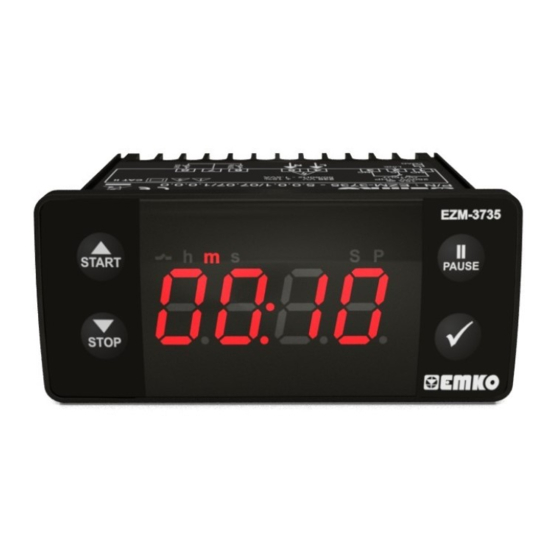
3735
EZM-
77 x 35 DIN Size
Digital Timer Controller
- 4 Digits Display
- Operation with One Set value
- Single Contact Output for Timing control (
)
ON /OFF
- External Start and Pause Input
- Start, Pause, Stop via front panel
- Password protection for programming section
- S
et value high limit boundaries
- Display can be adjusted to show Seconds, Minutes and Hours
-
Programmable Time Bases (Milliseconds, Seconds, Minutes, Hours)
- Adjustable internal buzzer according to Timer Stop status.
Instruction Manual. ENG EZM-3735 01 V02 09/14
Advertisement
Table of Contents

Summary of Contents for Z-TRAUQ EZM-3735
- Page 1 - Password protection for programming section et value high limit boundaries - Display can be adjusted to show Seconds, Minutes and Hours Programmable Time Bases (Milliseconds, Seconds, Minutes, Hours) - Adjustable internal buzzer according to Timer Stop status. Instruction Manual. ENG EZM-3735 01 V02 09/14...
- Page 2 1.Preface EZM-3735 Programmable Timer can be used in package machines, production and quality control rollers, and can be adapted easily to all mechanical construction and automation system. Some application fields which they are used are below: Application Fields Package machines,...
- Page 3 1.4 Warranty Z-TRAUQ INC warrants that the equipment delivered is free from defects in material and workmanship. This warranty is provided for a period of two years. The warranty period starts from the delivery date. This warranty is in force if duty and responsibilities which are determined in warranty document and instruction manual performs by the customer completely.
-
Page 4: General Description
Mounting Clamp Front Panel IP65 protection Panel Surface NEMA 4X (maximum thickness 15 mm / 0.59 inch) 2.1 Front View and Dimensions of EZM-3735 Digital Timer Maximum 15 mm / 0.59 inch START PAUSE STOP 65 mm / 2.56 inch 76 mm / 3 inch 6 mm / 0.24 inch... -
Page 5: Electrical Wiring Diagram
2.3 Panel Mounting 1-Before mounting the device in your panel, 3- Insert the mounting clamps to the fixing sockets make sure that the cut-out is of the right size. that located left and right sides of device and make the unit completely immobile within the panel 2-Insert the device through the cut-out. -
Page 6: Supply Voltage Input Connection Of The Device
4.1 Supply Voltage Input Connection of the Device Make sure that the power supply voltage is the same Power Supply Connection indicated on the instrument. Switch on the power supply only after that all the electrical connections have been completed. Supply voltage range must be determined in order. - Page 7 5.Front Panel Definition and Accessing to the Menus 5 6 7 8 10 11 BUTTON DEFINITIONS 1. Increment Button and Start Button : ** It is used to increase the value in the Set screen and Programming mode. ** It is used for Start the Timer in the Main Screen. 2.
-
Page 8: Programming Mode Parameter List
6. Changing and Saving Timing Set Value Main Operation Screen SET Value Screen Timer set value can be When Enter button pressed ‘’S’’ led will changed with increment and be active and temperature set value will decrement buttons. be displayed. Main Operation Screen When Enter button pressed Timing set ‘’S’’... - Page 9 Buzzer Function Selection Parameter ( Default = 0 ) if this parameter is selected 0, Buzzer is inactive. Adjustable 16 different buzzer sounds. It can be adjusted from 0 to16. Buzzer is active during this time ( Default = Buzzer stays active during this time. It can be adjusted from 1 to 99 seconds When this parameter is 1, if decrement button is pressed, is observed.
- Page 10 6.3 Operation Graphics of ESM-3735 Digital Timer 1.Control diagram using Start / Stop buttons 1.1 Ifi Start type s selected as 1.1.1 If downcount =1 and the control diagram is shown in Figure 1.1 1.1.2 If downcount =1 and the control diagram is shown in Figure 1.2 Power Power Output...
- Page 11 2.Control diagram using Start / Stop buttons 2.1 Ifi Start type s selected as 2.1.1 If Downcount =1 and the control diagram is shown in Figure 2.1 2.2.2 If Downcount =1 and the control diagram is shown in Figure 2.2 Power Power Output...
- Page 12 3.Control diagram using External Digital Start Input. is selected as If Start type 3.1.1 If Downcount =1 and the control diagram is shown in Figure 3.1 3.1.2 If Downcount =1 and the control diagram is shown in Figure 3.2 Power Power Output Output...
- Page 13 4.Control diagram using External Digital Start Input. is selected as If Start type 4.1.1 If Downcount =1 and the control diagram is shown in Figure 4.1 4.1.2 If Downcount =1 and the control diagram is shown in Figure 4.2 Power Power Output Output...
- Page 14 6.5 Entering the Programming Mode, Changing and Saving Parameters Main Operation Screen PAUSE PAUSE When Enter button is pressed for 5 Note1: If programming Programming Mode seconds, “P” led starts to blink. If mode accessing Entering Screen programming mode entering password is 0, Press Enter button to password is different from 0,...
- Page 15 7. Specifications Device Type : Digital Timer Housing & Mounting : 76mm x 34.5mm x 71mm plastic housing for panel Mounting. Panel cut-out is 71x29mm. Protection Class : Ip65 at front, Ip20 at rear. Weight : Approximately 0.20 Kg. Environmental Ratings : Standard, indoor at an altitude of less than 2000 meters with non condensing humidity.
- Page 16 Input 07 Digital Input All order information of EZM-3735 Digital Timer are given in the table above. User may form appropriate device configuration from information and codes therein and convert it to the ordering codes. Firstly, supply voltage then other specifications must be determined.
Need help?
Do you have a question about the EZM-3735 and is the answer not in the manual?
Questions and answers