Table of Contents
Advertisement
Available languages
Available languages
Quick Links
Advertisement
Chapters
Table of Contents
Troubleshooting

Related Manuals for WM aquatec BioLite

Summary of Contents for WM aquatec BioLite
- Page 1 UV-LED | WASSERDESINFEKTION UV-LED | WASSERDESINFEKTION ↗ BETRIEBSANLEITUNG biolite® UV-C Desinfektionseinheit ↗ OPERATION MANUAL biolite® UV-C disinfection unit ↗ INSTRUCTIONS D‘UTILISATION biolite® UV-C dispositif de désinfection...
- Page 2 Lieber WM aquatec Kunde, herzlichen Glückwunsch zum Kauf Ihrer biolite®. Sie halten hiermit ein innovatives Produkt in der Hand, welches zukunftsweisend und dennoch schon heute verfügbar ist. Bei sachgemäßem Gebrauch und einem ganzheitlich hygienisch betriebenen Frischwassersystem garantieren wir Ihnen zu jeder Zeit, an jedem Ort der Welt, hygienisch einwandfreies Trinkwasser. Tipps zum ganzheitlich hygienischen Betrieb Ihres Frischwassersystems fi nden Sie auch in dieser Betriebsanleitung.
-
Page 3: Table Of Contents
Gewichte und Abmessungen....................3.3.6 Elektrische Energieversorgung .................... 3.3.7 Betriebs- und Umgebungsbedingungen ................3.3.8 Empfohlener Flächenraum zur Installation der biolite® ..........Bedien- und Signalelemente ....................3.4.1 Lage von Bedien- und Signalelementen ................3.4.2 Signal-LED mit Signalhupe ....................4. Installation und Inbetriebnahme.......... - Page 4 4.3.5 Energieversorgung......................... 4.3.6 Elektrischer Anschluss ......................Erstinbetriebnahme ....................... 4.4.1 Sichtkontrolle .......................... 5. Betrieb ..................Sicherheitsvorschriften ......................Anforderungen an „Bediener“ der biolite® ................. Prüfungen vor dem Einschalten ................... Einschalten ..........................Sichtkontrolle .......................... Betriebsmodi ........................... 5.6.1 Standbymodus ........................5.6.2 Betriebsmodus ........................5.6.3 Reservemodus ........................
-
Page 5: Grundlegende Angaben
Ansprüche auf Schadenersatz, gleich aus welchem Rechtsgrund derartige Ansprüche hergeleitet werden, sind ausgeschlossen. Es wird empfohlen, bei Unklarheiten oder speziellen Fragen zur Montage, Inbetriebnahme, Betrieb, Wartung etc. - die Unterstützung ihres Fachhändlers/Werkstatt oder direkt der Fa. WM aquatec GmbH & Co. KG in Anspruch zu nehmen. 1.4.1 Reparaturen/Beschädigungen Reparaturen am Produkt sind ausschließlich vom Hersteller durchzuführen. -
Page 6: Sicherheit
Information! Wenden Sie sich bei offenen Fragen an den Ansprechpartner ihres Fachhändlers/Werkstatt oder direkt an die Fa. WM aquatec GmbH & Co. KG. 2.2 Verbot eigenmächtiger Veränderungen des Produkts Die Sicherheit des Produkts kann durch Umbauten oder Veränderungen jeglicher Art beeinträchtigt werden. -
Page 7: Symbole, Die An Der Anlage Angebracht Sind
2.4.1 Symbole, die an der Anlage angebracht sind Symbol Erklärung Vorsicht vor ultravioletter (UV-C) Strahlung UV-C Strahlung Tabelle 1: Symbole, die an der Anlage angebracht sind 2.5 Mindest-Qualifikationen im Umgang mit dem Produkt Tätigkeit Mindest-Personenqualifikation Handwerklich versierte Personen mit Erfahrungen Montage/Inbetriebnahme elektrischer Installationen im Kleinspannungsbereich Personen, die über die Betriebsanleitung instruiert... -
Page 8: Risiken
Zudem können eingetragene Schmutzstoffe die Strahlungsintensität beeinfl ussen, wenn sich diese vor der Lichtquelle ablagern. Ebenso kann es, je nach Wasserqualität und Temperatur des Wassers, vor der biolite® (z.B. im Frischwassertank) sowie in den Leitungen nach der biolite® zu einer Wiederverkeimung des desinfi zierten Wassers kommen. -
Page 9: Beschreibung Der Biolite
Onboard-Monitoring durch Signalgebung und integrierte Funktions-, Lebensdauer- sowie Temperaturüberwachung • inkl. Anschlussmaterial (elektrisch & wasserseitig) 3.1.3 Intelligentes Onboard-Monitoring Ein sicherer Betrieb der biolite® ist durch integrierte Strom- bzw. Funktionsüberwachung, Temperaturüberwa- chung, Lebensdauerüberwachung und Signalgebung (optisch & akustisch) sichergestellt. - 9 -... -
Page 10: Übersicht Und Lieferumfang
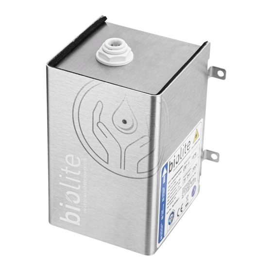
3 x Abzweigverbinder Abbildung 2: Lieferumfang Pos. Bezeichnung Pos. Bezeichnung biolite® UV-C LED Desinfektionseinheit Service-Card Wasseranschluss Eingang (IN) Betriebsanleitung Wasseranschluss Ausgang (OUT) Anschluss-Set Wasser Anschlusskabel (1,5 m) Anschluss-Set Elektrik Tabelle 3: Lieferumfang - 10 -... -
Page 11: Technische Daten
Tabelle 5: Anschlüsse Wasser Kompatible Anschluss-Adapter finden Sie im Kapitel Ersatzteile und Zubehör (S.29), im Zubehörfachhandel sowie auf der Homepage des Herstellers www.wm-aquatec.de. 3.3.4 Anschlüsse Elektrik Die biolite® ist bestimmt für den Betrieb mit folgenden elektr. Anschlüssen Bezeichnung im Lieferumfang Abzweigverbinder (Aderquerschnitt 0,5 ...1,5... -
Page 12: Gewichte Und Abmessungen
3.3.5 Gewichte und Abmessungen Gewicht 0,9 kg Breite x Höhe x Tiefe 113x159x105 mm Durchmesser Befestigungs-Löcher 5,2 mm 78 mm Tabelle 7: Gewichte und Abmessungen 104 mm 3.3.6 Elektrische Energieversorgung Spannung 12 -18 VDC Strom <0,01 A (Standby)/1,2 A (Betrieb) Leistungsaufnahme max. -
Page 13: Empfohlener Flächenraum Zur Installation Der Biolite
3.3.8 Empfohlener Flächenraum zur Installation der biolite® Für Installationsarbeiten und zur ergonomischen Bedienung wird folgender Platzbedarf zur Installation empfohlen: 20 x 30 x 20 cm (B x H x T) Abbildung 3: Benötigter Flächenraum zur Installation der biolite® - 13 -... -
Page 14: Bedien- Und Signalelemente
Tabelle 16: Lage von Bedien- und Signalelementen 3.4.2 Signal-LED mit Signalhupe Die Signal-LED ist auf der Vorderseite des biolite® Gehäuses angebracht und leuchtet in den Farben Grün und Rot (siehe Abbildung 4). Beim Ertönen der Signalhupe ist stets die Wasserentnahme zu stoppen und die biolite®... -
Page 15: Installation Und Inbetriebnahme
• UV-C Strahlung kann Haut- u. Augenschäden verursachen. • Öffnen Sie niemals das Gehäuse der biolite®. • Schauen Sie nie im eingeschalteten Zustand der biolite® in die Öffnungen der Wasseranschlüsse. • Betreiben Sie die biolite® nur im unbeschädigten und geschlossenen Zustand des Gehäuses. -
Page 16: Installation Und Inbetriebnahme
• Vergewissern sie sich, dass vor/hinter der Befestigungsfl äche keine anderen Versorgungsleitungen (Strom, Gas etc.) beschädigt werden. • Den benötigten Flächenraum der biolite® fi nden Sie im Kapitel Technische Daten (S.11) • Der Aufstellort muss trocken und sauber sein. • Die Umgebungsbedingungen für Lagerung & Betrieb müssen erfüllt werden (siehe Kapitel Technische Daten (S.11)). -
Page 17: Installation Gehäuse
Befestigen Sie die biolite® mit 4 geeigneten Schrauben senkrecht an einer dafür geeigneten Wand. Die Durchfl ussrichtung muss von unten nach oben erfolgen! Einen geeigneten Hinweis fi nden Sie auch auf dem Typenschild der biolite® (Abbildung 6). Überprüfen Sie die durchgeführte Arbeit auf Festigkeit der Verbindung. Abbildung 6: Installation Gehäuse 4.3.3 Anschluss an die Wasserleitungen... - Page 18 Abbildung: 7 Abbildung: 8 Abbildung: 9a Abbildung: 9b - 18 -...
- Page 19 Abbildung: 10a Abbildung: 10b Abbildung: 11 - 19 -...
-
Page 20: Lösen Von Einsteck-Verbindern
Abbildung: 12a Abbildung: 12b 4.3.4 Lösen von Einsteck-Verbindern Sollte es notwendig sein, eine Einsteck-Verbindung zu lösen, gehen Sie bitte wie folgt vor (Abbildung 13). Ent- fernen Sie zuerst den Sicherungs-Ring (1). D as Halteelement mit den Fingern oder unter Zuhilfenahme einer Lösehilfe zurückdrücken und festhalten (2). -
Page 21: Energieversorgung
Schalten Sie die biolite® über den Hauptschalter aus (siehe auch Kapitel Lage von Bedien- und Signalelementen (S.14)). Schließen Sie anhand Tabelle 16 die drei Adern (Litzen) der biolite® mittels den im Lieferumfang enthaltenen Abzweigverbindern an die Spannungsversorgung und an die Pumpe an (Abbildung 15+16). - Page 22 Abbildung: 15 Abbildung: 16 KLICK Abbildung: 17 Abbildung: 18 - 22 -...
-
Page 23: Erstinbetriebnahme
Schließen Sie alle Verbraucher (Armaturen) und vergewissern Sie sich, dass die Pumpe aus ist und kein Wasser fördert. 5.4 Einschalten Schalten Sie die biolite® über ihren Hauptschalter an. Ein kurzes Hupen der Signalhupe sowie ein Aufblinken der roten und grünen Signal-LED signalisieren deren Funktionsfähigkeit. - 23 -... -
Page 24: Sichtkontrolle
Signalhupe über die Signalisierung der Signal-LED. Beachten Sie hierzu auch das Kapitel Fehlersuche und Störungsbeseitigung (S.25). 5.8 Überwinterung Sorgen Sie im Winter und bei Minus-Temperaturen dafür, dass das Wasser in der biolite® nicht gefriert bzw. entfernen Sie das Wasser zuvor (siehe auch Kapitel Deinstallation/Außerbetriebnahme (S.27)). - 24 -... -
Page 25: Fehlersuche Und Störungsbeseitigung
• UV-C Strahlung kann Haut- u. Augenschäden verursachen. • Öffnen Sie niemals das Gehäuse der biolite®. • Schauen Sie nie im eingeschalteten Zustand der biolite® in die Öffnungen der Wasseranschlüsse. • Betreiben Sie die biolite® nur im unbeschädigten und geschlossenen Zustand des Gehäuses. -
Page 26: Störungsbeseitigung
Nach erfolgreichem Quittieren der Meldung befinden Sie sich im Reservemodus. Die Signal-LED blinkt nun abwechselnd rot/grün (im Standby sowie im Betrieb). Über die biolite® können jetzt noch maximal 100 Stunden Wasser entnommen werden. Danach geht die biolite® auf Störung/Defekt und das Produktlebensende ist erreicht. -
Page 27: Reinigung
• UV-C Strahlung kann Haut- u. Augenschäden verursachen. • Öffnen Sie niemals das Gehäuse der biolite®. • Schauen Sie nie im eingeschalteten Zustand der biolite® in die Öffnungen der Wasseranschlüsse. • Betreiben Sie die biolite® nur im unbeschädigten und geschlossenen Zustand des Gehäuses. -
Page 28: Vorbereitungen
Schalten Sie die biolite® über den Hauptschalter aus. • • Vergewissern Sie sich, dass sich kein Wasser in der biolite® und in den Wasser führenden Schläuchen befi ndet. • Entfernen Sie die Sicherungen aller relevanten Stromkreise (Spannungsversorgung biolite®, Pumpe etc.). -
Page 29: Ersatzteile Und Zubehör
10. ERSATZTEILE UND ZUBEHÖR 10.1 Ersatzteilliste Benennung Verwendung Artikelnummer Anschluss der bordseitigen Anschluss-Set Wasser BLUVC0812-ASW Wasserleitungen an biolite® Anschluss der bordseitigen elektr. Anschluss-Set Elektrik BLUVC0812-ASE Anschlusskabel an biolite® Tabelle 20: Ersatzteilliste 10.2 Zubehörliste Benennung Verwendung Artikelnummer Vorfiltration des Wassers bei Wasserfilter-Set „Mobile Edition“... - Page 30 Dear WM aquatec customer, Congratulations on the purchase of your biolite®. You are holding an innovative product in your hand, which is trendsetting and yet available today. With proper use and a hygienically operated fresh water system, we guarantee you healthy and pure perfect drinking water at any time, anywhere in the world.
- Page 31 3.3.6 Electrical power supply ......................3.3.7 Operating and ambient conditions ..................3.3.8 Recommended space required for installation of the biolite® ......... Control and signal elements ....................3.4.1 Position of control and signal elements ................3.4.2 Signal LED with signal horn ....................
- Page 32 Storage ............................. 9. Disposal ................... 10. Spare parts and accessories ........... 10.1 Spare parts list ........................10.2 Accessories list ........................11. Installation example parallel connection of the biolite® .... 12. Installation example for surface water treatment ....- 32 -...
-
Page 33: Basic Information
Claims for damages, irrespective of the legal basis on which such claims are derived, are excluded. It is recommended to contact your specialist dealer/workshop or directely WM aquatec GmbH & Co. KG in the event of any uncertainties or specific questions regarding installation, commissioning, operation, maintenance etc. -
Page 34: Safety
Information! If you have any questions, contact your specialist dealer/workshop or WM aquatec GmbH & Co. KG. 2.2 Prohibition of unauthorised modifications to the product The safety of the product can be affected by any kind of conversion or modification. -
Page 35: Symbols Attached To The Product
2.4.1 Symbols attached to the product Symbol Symbol explanation Beware of ultraviolet (UV-C) radiation UV-C radiation Table 1: Symbols attached to the product 2.5 Minimum qualifications for handling the product Activity Minimum qualification Skilled personnel with experience of electrical Assembly/Commissioning installations in the low voltage range Persons who have been instructed about the Operation/Cleaning... -
Page 36: Risks
Depending on the water quality and the temperature of the water before the biolite® (e.g. in the fresh water tank) as well as in the pipes after the biolite®, a germination/re-germination of the water can also occur. -
Page 37: Description Of The Biolite
3. DESCRIPTION OF THE BIOLITE® 3.1 General description biolite® UV-C disinfection unit Thanks to the innovative UV-C LED technology, biolite® UV disinfection devices from WM aquatec have an extraordinarily high disinfection performance with a compact design. In contrast to the previous UV technology, there are no environmentally dangerous medium-pressure mercury-vapor lamps here, but the latest UV-C LED technology, which brings enormous advantages with it. -
Page 38: Overview And Scope Of Delivery
Image 2: Scope of delivery Pos. Designation Pos. Designation biolite® UV-C LED water disinfection unit Service-Card Water connection input (IN) Operating instructions Water connection output (OUT) Water connection set Connection cable (1.5 m) Electrical connection set Table 3: Scope of delivery... -
Page 39: Technical Data
3.3.2 Type plate The type plate is located on the right side of the product housing 3.3.3 Water connections The biolite® is designed for operation with the following water connections Description Included in the scope of delivery Plug-in hose nozzle 9/10 mm Plug-in hose nozzle 12/13 mm Plug-in angle 90 °... -
Page 40: Weights And Dimensions
3.3.5 Weights and dimensions Weight 0,9 kg Width x Height x Depth 113x159 x105 mm Diameter of mounting holes 5,2 mm 78 mm Table 7: Weights and dimensions 104 mm 3.3.6 Electrical power supply Voltage 12 -18 VDC Current <0,01 A (Standby)/1,2 A (Operating) Power consumption max. -
Page 41: Recommended Space Required For Installation Of The Biolite
Store and operate the product only inside a closed building, install it as vibration-free as possible, avoid heat accumulation and protect it from moisture. 3.3.8 Recommended space required for installation of the biolite® For installation and ergonomic operation, the following space... -
Page 42: Control And Signal Elements
3.4.2 Signal LED with signal horn The signal LED is located on the front of the biolite® housing and lights up in green and red (see image 4). When the signal horn sounds, always verify biolite® to interpret the optical signal of the signal LED. For the meanings of the optical messages please refer to the chapter Signal messages (p.53). -
Page 43: Installation And Commissioning
- if not, extend them or strip the connection cable of the biolite® accordingly. the „activation“ of the biolite® must be carried out by means of a signal line through the water delivery unit (pump). For pressure pumps with pressure switch this is the cable leading to the pump drive (+12 ... -
Page 44: Installation And Commissioning
Image 5: Installation location Information! The biolite® may only be installed behind the pump, in front of the fi rst pipe branch • (image 5). • The load capacity of the mounting surface (wall) must be suitable for the weight of the product. -
Page 45: Installing The Housing
Fix the biolite® with 4 suitable screws vertically to a suitable wall. The fl ow direction must be from bottom to top. An explanatory note can also be found on the type plate of the biolite® (image 6). Check the strength of the connection. - Page 46 Image: 7 Image: 8 Image: 9a Image: 9b - 46 -...
- Page 47 Image: 10a Image: 10b Image: 11 - 47 -...
-
Page 48: Disconnecting Plug-In Connectors
Image: 12a Image: 12b 4.3.4 Disconnecting plug-in connectors If it is necessary to disconnect a plug-in connection, please proceed as follows (image 13). First remove the locking clip (1). Press the retaining element back with your fi ngers or with the help of a release aid and hold it there (2). -
Page 49: Power Supply
(see also chapter Position of control and signal elements (p.42)). Use the table 16 to connect the 3 wires (strands) of the biolite® to the supply voltage and to the pump using the wire-tap connectors included in the scope of delivery (images 15 and 16). - Page 50 Image: 15 Image: 16 CLICK Image: 17 Image: 18 - 50 -...
-
Page 51: Initial Commissioning
Close all consumers (taps) and make sure that the pump is off and not pumping water. 5.4 Switching on Switch on the biolite® at its main switch. A short honk of the signal horn as well as the flashing of the red and green signal LED indicates that the device is working properly. -
Page 52: Visual Inspection
5.6.1 Standby mode As soon as the biolite® is switched on via the main switch and the power supply is guaranteed, it is in standby mode. This can be recognized by the green flashing signal LED on the front of the housing (see also chapter Signal messages (p.53)). -
Page 53: Troubleshooting And Error Rectification
6.2 Requirements for the person performing the work The troubleshooting of the biolite® must either be carried out by qualified personnel in a workshop/shipyard or by a technically experienced person (see also chapter Minimum qualifications for handling the product (p.35)). -
Page 54: Troubleshooting
(in standby as well as in operation mode). Starting from now you can still use the biolite® for maximum 100 hours (time of water extraction). After this time the life end of the biolite® is reached and it must be disposed of accordingly. -
Page 55: Cleaning
• UV-C radiation can cause damage to skin and eyes. • Never open the housing of biolite®. • Never look into the openings of the water connections when the biolite® is switched on. • Only operate the biolite® when the housing is undamaged and closed. -
Page 56: Preparations
• Remove the water pipes from the water connections of the biolite® (image 19). First remove the locking clip (1). Press the retaining element back with your fi ngers or with the help of a release aid and hold it there (2). The inserted tube/hose can now be removed (3). -
Page 57: Spare Parts And Accessories
Water connection set BLUVC0812-ASW pipes to biolite® Connection of the on-board electri- Electrical connection set BLUVC0812-ASE cal connection cables to biolite® Table 20: Spare parts list 10.2 Accessories list Designation Part number Pre-filtration of water during tank Water filter set „Mobile Edition“... - Page 58 Cher client WM aquatec, Félicitations pour l‘achat de votre biolite®. Vous tenez dans votre main un produit innovant, qui est à la pointe de la technologie et pourtant disponible aujourd‘hui. À une utilisation appropriée du dispositif et avec un système d‘eau claire exploité de manière hygiénique, nous vous garantissons une eau potable parfaitement saine et sûre à...
- Page 59 2.7.1 Réduction des risques ......................2.7.2 Signaux d‘alerte et de perturbation ..................3. Description de la biolite® ............Description générale de l‘unité de désinfection UV-C biolite® ........3.1.1 Fonctionnement de la désinfection par UV-C ..............3.1.2 Avantages de biolite® ......................
- Page 60 10. Pièces de rechange et accessoires ........... 10.1 Liste des pièces de rechange ....................10.2 Liste des accessoires ......................11. Exemple d‘installation connexion parallèle de la biolite® ..12. Exemple d‘installation pour le traitement des eaux de surface ... - 60 -...
-
Page 61: Informations De Base
Les demandes de dommages et intérêts, quel que soit la base juridique de ces demandes, sont exclues. Il est recommandé de contacter votre revendeur/atelier spécialisé ou directement WM aquatec GmbH & Co. KG en cas d‘incertitudes ou de questions spécifiques concernant l‘installation, la mise en service, l‘exploitation, la maintenance, etc. -
Page 62: Sécurité
Information! Si vous avez des questions, contactez votre revendeur/atelier spécialisé ou WM aquatec GmbH & Co. KG. 2.2 Interdiction de modifications non autorisées du produit La sécurité du produit peut être affectée par tout type de conversion ou de modification. -
Page 63: Symboles Apposés Sur Le Système
2.4.1 Symboles apposés sur le système Symbole Explication du symbole Attention au rayonnement ultraviolet (UV-C) Rayonnement UV-C Tableau 1: Symboles apposés sur le produit 2.5 Qualifications minimales pour la manipulation du produit Activité Qualification minimale Personnel qualifié ayant une expérience des installa- Montage/Mise en service tions électriques dans le domaine de la basse tension Personnes ayant reçu des instructions sur le mode... -
Page 64: Risques
De plus, les contaminants introduits peuvent infl uencer l‘intensité du rayonnement s‘ils sont déposés devant la source de lumière. Selon la qualité et la température de l‘eau avant la biolite® (par exemple dans le réservoir d‘eau claire) ainsi que dans les tuyaux après la biolite®, une germination/re-germination de l‘eau peut également se produire. -
Page 65: Description De La Biolite
3. DESCRIPTION DE LA BIOLITE® 3.1 Description générale de l‘unité de désinfection UV-C biolite® Grâce à la technologie innovante LED UV-C, les dispositifs de désinfection UV biolite® de WM aquatec se distingu- ent par une puissance de désinfection extraordinairement élevée et un design compact. -
Page 66: Aperçu Et Contenu De La Livraison
Image 2: Volume de la livraison Pos. Désignation Pos. Désignation biolite® UV-C dispositif de désinfection Carte de service Raccordement à l‘eau Entrée (IN) Instructions d‘utilisation Raccordement à l‘eau Sortie (OUT Kit de raccordement de l‘eau Câble de connexion (1.5m) Kit de raccordement électrique... -
Page 67: Données Techniques
3.3.2 Plaque signalétique La plaque signalétique est située sur le côté droit du boîtier du produit 3.3.3 Raccordements à l‘eau La biolite® est conçue pour fonctionner avec les branchements d‘eau suivants Description Inclus dans le contenu de la livraison Embout tuyau enfichable 9/10 mm Embout tuyau enfichable 12/13 mm Angle d‘enfichage 90 °... -
Page 68: Poids Et Dimensions
3.3.5 Poids et dimensions Poids 0,9 kg Largeur x Hauteur x Profondeur 113 x159 x105 mm Diamètre des trous de fi xation 5,2 mm 78 mm Tableau 7: Poids et dimensions 104 mm 3.3.6 Alimentation en énergie électrique Tension 12 -18 VDC Courant <... -
Page 69: Espace Nécessaire Pour L'installation De La Biolite
Pour les travaux d‘installation et le fonctionnement ergonomique, il est recommandé de respecter les exigences suivantes en matière d‘espace pour l‘installation: 20 x 30 x 20cm (L x H x P) Image 3: Espace nécessaire pour l‘installation de la biolite® - 69 -... -
Page 70: Éléments De Commande Et De Signalisation
3.4.2 Ssignalisation LED et sonore La LED de signalisation est située sur le recto du boîtier de la biolite® et s‘allume en vert et en rouge (voir image 4). Lorsque le signal sonore retentit, vérifi ez toujours la biolite® pour interpréter le signal optique de la LED de signalisation. -
Page 71: Installation Et Mise En Service
4. INSTALLATION ET MISE EN SERVICE Information! L‘installation et la mise en service de la biolite® doivent être effectuées par du personnel spécialisé dans un atelier ou par une personne techniquement compétente (voir également le chapitre Qualifica- tions minimales pour la manipulation du produit (p.63)). -
Page 72: Installation Et Mise En Service
Image 5: Lieu d‘installation Information! La biolite® ne peut être installée que derrière la pompe, avant la première branche du tuyau • (image 5). • La capacité de charge de la surface de montage (mur) doit être adaptée au poids du produit. -
Page 73: Installation Du Boîtier
(image 10a). b. dans les angles d‘enfi chage de 90° inclus dans la livraison et ensuite dans la biolite® (image 10b). Dans les deux cas, sécurisez toutes les connexions avec les bagues de verrouillage incluses dans la livraison (Image 11). - Page 74 Image: 7 Image: 8 Image: 9a Image: 9b - 74 -...
- Page 75 Image: 10a Image: 10b Image: 11 - 75 -...
-
Page 76: Détacher Les Embouts Tuyau Enfichables
Image: 12a Image: 12b 4.3.4 Détacher les embouts tuyau enfi chables S‘il est nécessaire de débrancher une connexion enfi chable, veuillez procéder comme suit (Image 13). Retirez d‘abord la bague de verrouillage (1). Repoussez l‘élément de soutient avec vos doigts ou à l‘aide d‘un outil de démontage et tenez-le fermement (2). -
Page 77: Alimentation Électrique
Éteignez la biolite® par l‘interrupteur principal (voir également le chapitre Position des éléments de commande et de signalisation (p.70)). Utilisez le tableau 16 pour raccorder les 3 fils (torons) de la biolite® à la tension d‘alimentation et à la pompe en utilisant les connecteurs de dérivation inclus dans la livraison (images 15 et 16). - Page 78 Image: 15 Image: 16 CLICK Image: 17 Image: 18 - 78 -...
-
Page 79: Mise En Service Initiale
5.4 Mise en marche Allumez la biolite® à l‘aide de son interrupteur principal. Un bref signal sonore et un clignotement de la LED rouge et verte indiquent que le système fonctionne correctement. - 79 -... -
Page 80: Inspection Visuelle
(p.81). 5.8 L’hivernage En hiver et à des températures inférieures à zéro, veillez à ce que l‘eau contenue par la biolite® ne gèle pas ou à ce que l‘eau soit préalablement évacuée (voir également le chapitre Désinstallation/Mise hors service (p.83)). -
Page 81: Dépannage Et Correction Des Erreurs
6.2 Exigences applicables à la personne qui effectue le travail Le dépannage de la biolite® doit être effectué soit par du personnel qualifié dans un atelier/un chantier naval, ou par une personne techniquement expérimentée (voir également le chapitre Qualifications minimales pour la manipulation du produit (p.63)). -
Page 82: Dépannage
Après avoir accusé réception du message, vous êtes en mode «survie». La LED de signalisation clignote main- tenant alternativement rouge/vert (en veille comme en fonctionnement). Désormais, on peut utiliser la biolite® pendant encore maximum 100 heures pour prélever de l‘eau. Après cela, la biolite® tombe en panne/défaut et la durée de vie du produit est terminé. -
Page 83: Le Nettoyage
8. DÉSINSTALLATION/MISE HORS SERVICE Information! La désinstallation/mise hors service de biolite® doit être effectuée soit par un personnel qualifié dans un atelier/chantier naval, soit par une personne techniquement expérimentée (voir également le chapitre Qualifications minimales pour la manipulation du produit (p.63)). -
Page 84: Préparatifs
Vérifi ez que l‘installation ne présente pas de fuites. Image: 19 8.4 Stockage • Pour stocker la biolite® en dehors de son lieu d‘utilisation, veuillez respecter les conditions de stockage du chapitre Conditions de fonctionnement et ambiantes (p.68). 9. ÉLIMINATION •... -
Page 85: Pièces De Rechange Et Accessoires
Kit de raccordement eau BLUVC0812-ASW bord à la biolite® Raccordement des câbles de conne- Kit de raccordement électrique BLUVC0812-ASE xion électrique à bord à la biolite® Tableau 20: Liste des pièces de rechange 10.2 Liste des accessoires Designation Utilisation Référence Pré-filtration de l‘eau lors du... -
Page 86: Installationsbeispiel Parallelschaltung Der Biolite
11. INSTALLATIONSBEISPIEL PARALLELSCHALTUNG DER BIOLITE® Parallelschaltung für höhere Durchfl ussraten 11. INSTALLATION EXAMPLE PARALLEL CONNECTION OF THE BIOLITE® Parallel connection for higher fl ow rates 11. EXEMPLE D‘INSTALLATION CONNEXION PARALLÈLE DE LA BIOLITE® Connexion parallèle pour des débits plus élevés ... -
Page 87: Installationsbeispiel Für Oberflächenwasseraufbereitung
Boîtier de filtre à eau (taille S) avec robinet d‘arrêt et cartouche de charbon actif (en option) biolite® UV-C Desinfektionseinheit BLUVC0812 biolite® UV-C disinfection unit biolite® UV-C dispositif de désinfection Tabelle 23: Installationsbeispiel für Oberflächenwasseraufbereitung Table 23: Installation example for surface water treatment/Tableau 23: Exemple d‘installation pour le traitement des eaux de surface - 87 -... - Page 88 ≥ WM AQUATEC GMBH & CO.KG URACHER STRASSE 22 ı DE-73268 ERKENBRECHTSWEILER ı TEL: +49 (0) 7026 / 93 210 90 ı FAX: +49 (0) 7026 / 93 210 98 MAIL: INFO@WM-AQUATEC.DE ı WWW.WM-AQUATEC.DE...
Need help?
Do you have a question about the BioLite and is the answer not in the manual?
Questions and answers