
Summary of Contents for GPS GPS-iDETECT-P
- Page 1 GPS-iDETECT-P Installation, Operation & Maintenance Manual www.globalplasmasolutions.com...
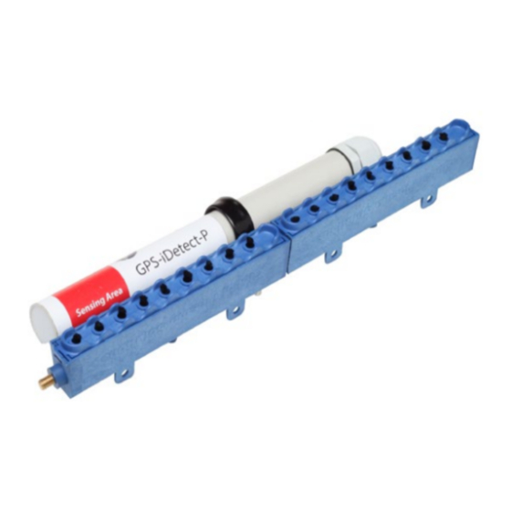
- Page 2 Mount the GPS-iDETECT-P to the GPS-iMOD bar using the included 1” coated pipe clamp and secure it to a GPS-iMOD section using a nut and bolt as shown in FIGURE 1. The sensor should be as close as possible to the ionization source.
- Page 3 5. Connect the line (L), neutral (N), and common wires (COM or C). See FIGURE 4. 6. Connect the normal open (NO) contact on the GPS-iDETECT-P to the “ON” contact on the GPS-iMOD power supply terminal block (see FIGURE 4).
- Page 4 BMS/BAS for remote monitoring, use 18/2 twisted pair, SHIELDED, plenum rated cable and connect to the “BAS Alarm” contact terminals inside the GPS-iMOD power supply. Connect the cable shield to the “BAS Alarm” ground contact (G) shown in FIGURE 5. The terminal block may be removed for ease of wiring.
- Page 5 3101 Yorkmont Road • Suite 400 Charlotte, NC 28208 980-279-5622 GPS, GPS-iDETECT-P and its logos are trademarks of Global Plasma Solutions, Inc. ©2020 Global Plasma Solutions, Inc. www.globalplasmasolutions.com 030120-GPSIDETECH-P-IOM REV A...
Need help?
Do you have a question about the GPS-iDETECT-P and is the answer not in the manual?
Questions and answers