Table of Contents
Advertisement
Quick Links
Advertisement
Table of Contents

Summary of Contents for RubyTech VC-450LR
- Page 1 VC-450LR Managed Industrial VDSL2 CO/CPE Modem. USER’S MANUAL...
- Page 2 In the interest of improving internal design, operational function, and/or reliability, RUBYTECH reserves the right to make changes to the products described in this document without notice. RUBYTECH does not assume any liability that may occur due to the use or application of the product(s) or circuit layout(s) described herein.
- Page 3 VC-450LR Managed Industrial VDSL2 CO/CPE Modem USER’S MANUAL Ver. B. 3 Use ONLY the dedicated power supply for your device. Connect the power to the right supply voltage (110V AC used for North America and 230V AC used for Europe. VC-450 supports 12 to 48 VDC dual power input (Redundant power)).
- Page 4 Internet access and advanced voice services including VoIP, over a standard copper telephone cable. VC-450LR is seen by many operators as an ideal accompaniment to a FTTP rollout, where for instance fiber optic is supplied direct to an apartment block and from there copper cable is used to supply residents with high-speed VDSL2.
-
Page 5: Table Of Contents
VC-450LR Managed Industrial VDSL2 CO/CPE Modem USER’S MANUAL Ver. B. 3 2.1 H ..............................8 ARDWARE NSTALLATION 2.2 P ............................8 INSTALLATION EQUIREMENTS 2.3 G .................................9 ENERAL ULES 2.4 C ..............................10 ONNECTING THE ODEM 2.5 C RJ-11 / RJ-45 P ..........................11 ONNECTING THE ORTS 2.5 P... - Page 6 VC-450LR Managed Industrial VDSL2 CO/CPE Modem USER’S MANUAL Ver. B. 3 4.3.6 Service Control.............................................33 4.3.7 CWNP (TR-069 Settings)........................................35 4.3.8 Internet Time............................................36 4.3.9 Restore Default.............................................37 4.4 S ................................38 TATUS ETUP 4.4.1 LAN Network............................................39 4.4.2 Ethernet..............................................40 4.4.3 WAN(Line) Statistics..........................................41 4.4.4 LAN Statistics............................................42 4.4.5 ARP.................................................43...
- Page 7 APPENDIX A: CABLE REQUIREMENTS......................................66 APPENDIX B: PRODUCT SPECIFICATION......................................69 APPENDIX C: TROUBLESHOOTING........................................72 APPENDIX E: COMPLIANCE INFORMATION....................................81 Warranty..................................................84 Chapter 1. Unpacking Information 1.1 Check List Thank you for choosing RubyTech VC-450LR Before installing the modem, please verify the contents inside the package.
- Page 8 VC-450LR Managed Industrial VDSL2 CO/CPE Modem USER’S MANUAL Ver. B. 3 Package Contents: 1 x Industrial VDSL2 Accessory Kit : 1 x DIN-Rail mounting plate, 2 x screws, 4 x Feet, 1 x CPE modem 6pin Terminal Block, 1 x 2pin Terminal Block Notes: 1.
-
Page 9: Hardware Installation
Installing the Modem 2.1 Hardware Installation This chapter describes how to install the modem, and establish the network connections. The VC-450LR may be installed on any level surface (e.g. a table or shelf). However, please take note of the following minimum site requirements before you begin. -
Page 10: General Rules
VC-450LR Managed Industrial VDSL2 CO/CPE Modem USER’S MANUAL Ver. B. 3 Avoid installing this device with radio amplifying stations nearby or transformer stations nearby. 2.3 General Rules Before making any connections to the modem, please note the following rules: Ethernet Port interface : RJ-45 ... - Page 11 VC-450LR Managed Industrial VDSL2 CO/CPE Modem USER’S MANUAL Ver. B. 3 Unused Unused 2.4 Terminal Block and DIN-Rail mount installation This section describes how to install the Terminal Block and DIN-Rail to the modem, if you do not install the DIN-Rail, please paste the 4 rubber feet at the bottom of the hulled to avoid scratches of metal housing.
-
Page 12: Rj-45 Ports
VC-450LR Managed Industrial VDSL2 CO/CPE Modem USER’S MANUAL Ver. B. 3 Figure 2.4.1 Figure 2.4.2 Figure 2.4.3 Figure 2.4.4 2.5 Connecting the RJ-11 / RJ-45 Ports The line port has 2 connectors: RJ-45 and terminal block. It is used to connect from VC-450(CO) using single pair phone cable to VC-450(CPE) bridge side (point to point solution). - Page 13 VC-450LR Managed Industrial VDSL2 CO/CPE Modem USER’S MANUAL Ver. B. 3 Figure 2.5.2 VC-450LR line ports straight connection Figure 2.5.1 VC-450LR line ports straight connection When inserting a RJ-11 plug, make sure the tab on the plug clicks into position to ensure that it is properly seated.
-
Page 14: Point To Point Application
VC-450LR Managed Industrial VDSL2 CO/CPE Modem USER’S MANUAL Ver. B. 3 2.6 Point to Point Application First a quick overview on a complete setup of LAN extender Master/Slave LAN extender. VC-450LR is a LAN extender leverages the extraordinary bandwidth promise of VDSL2 technology (max. 100Mbps Symmetric) (Figure 2.6) - Page 15 VC-450LR Managed Industrial VDSL2 CO/CPE Modem USER’S MANUAL Ver. B. 3 Figure 2.6 VC-450LR Point to Point application...
- Page 16 VC-450LR Managed Industrial VDSL2 CO/CPE Modem USER’S MANUAL Ver. B. 3 Figure 2.6 VC-450LR industrial-grade application...
- Page 17 2.6.1 Connect the VC-450LR(Master) and the VC-450LR(Slave) to the Line The objective for LAN extender is to pass high speed data over a twisted pair cable. In the setup, connect VC-450LR(Master) to VC-450LR (Slave) through phone wire(24~26 AWG) or line simulator or any other hardware representation of a cable network, with or without noise injection and crosstalk simulations.
-
Page 18: Chapter 3. Hardware Description
VC-450LR Managed Industrial VDSL2 CO/CPE Modem USER’S MANUAL Ver. B. 3 Chapter 3. Hardware Description This section describes the important parts of the VC-450LR. It features the front panel and rear panel. VC-450LR Outward 3.1 Front Panel... -
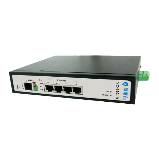
Page 19: Front Indicators
VC-450LR Managed Industrial VDSL2 CO/CPE Modem USER’S MANUAL Ver. B. 3 The figure shows the front panel. (Figure 3.1) Figure 3.1 Front Panel(VC-450LR) 3.2 Front Indicators The Modem has Seven LED indicators. The following Table shows the description. (Table 3-1) - Page 20 Note: It is normal for the connection between two VC-450LR to take up to 3 minutes, due to VC-450LR(Master) connect VC- 450LR(Slave) to establish a link mechanism in auto-speed, with detects and calculates Master and Slave both PBO and PSD level, noise levels and other arguments for getting a better connection.
-
Page 21: Rear Panel
VC-450LR Managed Industrial VDSL2 CO/CPE Modem USER’S MANUAL Ver. B. 3 The reset buttons allows users to reboot the LAN VC-450LR or load the default settings. Reset Tact Switch Button Press and hold for 1-5 seconds: Reboot the VC-450LR Press over 5 seconds: Load the default settings External switching Power Adapter: Input: AC 85~240Volts/50~60Hz. -
Page 22: Side Panel
Wiring the dual Power Inputs The VC-450LR has two sets of power inputs, power 1 and power 2, which are located on the VC-450LR’s side panel. Power 1 pins are the bottom two contacts of the upper 6-contact terminal block and power 2 pins are the only two contacts on the lower 2-contact... - Page 23 Protection function automatically. DC power will not be able to directly through the machine. 2. Please note that if the DC power current exceeds 3A, VC-450LR will enable Overload Current Protection function automatically. DC power will not be able to directly through the machine.
- Page 24 1. State 1 always happens before State 2. 2. Protection means enable Reverse Polarity Protection function. 3. Please note that if use different DC voltage, higher voltage will feeding to VC-450LR. 4. Please note that the warranty is void if DC 48V power input is exceeded.
- Page 25 VC-450LR Managed Industrial VDSL2 CO/CPE Modem USER’S MANUAL Ver. B. 3 The VC-450LR has a set of relay outputs. The relay contact uses of the terminal block’s contacts located on the VC-450LR’s side panel. Refer to the following table shows how to connect the wires to the terminal block connector. In this section, we illustrate the meaning of the two contacts used to connect the relay contact.
- Page 26 VC-450LR is designed to enhance EMS performance by grounding. VC-450LR come with metal DIN-Rail brackets for grounding the switches. For optimal EMS performance, connection of the right of the VC-450LR side panel ground lug to the grounding point. Before user installed power and device, please read and follow these essentials: ...
-
Page 27: Chapter 4. Configure The Vc-450Lr Via Web Management Menu
Chapter 4. Configure the VC-450LR via Web management menu The VC-450LR provides a built-in HTML based management interface that allows configuration of the VC-450LR via Internet Browser. Best viewed using Chrome or Firefox browsers. In order to use the web browser to configure the device, you may need to allow: ... -
Page 28: Basic Setup
VC-450LR Managed Industrial VDSL2 CO/CPE Modem USER’S MANUAL Ver. B. 3 4.1 BASIC Setup 4.1.1 Login Webpage The default username and password are “admin”. Figure 4.1.1 Login Webpage 4.1.2 Display status When the device is running, the status page will display the device informa ons (Hardware/So ware Version,... -
Page 29: Select The Menu Level
MAC Address, and System Up Time), as shown in Figure 4.1.2. Figure 4.1.2 Device Info 4.2 Select the Menu Level There is an easy Setup for end users at the setup of VC-450LR with System, Status, xDSL, LAN, Qos, Applica ons,... -
Page 30: System
VC-450LR Managed Industrial VDSL2 CO/CPE Modem USER’S MANUAL Ver. B. 3 Home, Logout for more detail configura ons Figure 4.2 Select the Menu Level 4.3 System Select “System”. The menu below will be used frequently. It includes the sub-menus of... -
Page 31: Configuration Backup
VC-450LR Managed Industrial VDSL2 CO/CPE Modem USER’S MANUAL Ver. B. 3 Backup Configura on Restore Update So ware Account Managemant Log level Logs Service 、 、 、 、 、 、 Control 、CWMP、Internet Time、Reboot、Restore Default. A screen is displayed as shown in Figure 4.3... -
Page 32: Configuration Restore
VC-450LR Managed Industrial VDSL2 CO/CPE Modem USER’S MANUAL Ver. B. 3 Figure 4.3.1 Configuration Backup 4.3.2 Configuration Restore To restore your configura on se ng value, click on the “Configura on Restore” link in the le naviga on bar. A screen is displayed as shown in Figure 4.3.2. -
Page 33: Update Software
VC-450LR Managed Industrial VDSL2 CO/CPE Modem USER’S MANUAL Ver. B. 3 Figure 4.3.2 Configuration Restore The screen contains the following detail: Click "Browse" to select a specific file name in preparation for modem settings Click “Update Settings” to start updating. -
Page 34: Account Management
VC-450LR Managed Industrial VDSL2 CO/CPE Modem USER’S MANUAL Ver. B. 3 Figure 4.3.3 Update Software Note: The update process takes about 12 minutes to complete, and your Broadband Modem will reboot. 4.3.4 Account Management To change or create passwords, click on the “Account Management” link in the le naviga on bar. A screen is displayed as shown in Figure 4.3.4. -
Page 35: Log Level
VC-450LR Managed Industrial VDSL2 CO/CPE Modem USER’S MANUAL Ver. B. 3 Figure 4.3.4 Account Management-Password 4.3.5 Log Level Click on the “Log level” link in the le naviga on bar, on the right page you will see how to enable Log or Log Server. -
Page 36: Service Control
VC-450LR Managed Industrial VDSL2 CO/CPE Modem USER’S MANUAL Ver. B. 3 Figure 4.3.5 Account Management – Log Level 4.3.6 Service Control Click on “Service Control” link in the le naviga on bar, on the right page you will see how to enable ACL. - Page 37 VC-450LR Managed Industrial VDSL2 CO/CPE Modem USER’S MANUAL Ver. B. 3...
-
Page 38: Cwnp (Tr-069 Settings)
VC-450LR Managed Industrial VDSL2 CO/CPE Modem USER’S MANUAL Ver. B. 3 Figure 4.3.6 Service Control – IP Address Configuration 4.3.7 CWNP (TR-069 Settings) Click on “CWMP” link in the left navigation bar to create TR-069 connection, and setup ACS URL/ ACS User Name/ACS Password and basic information. -
Page 39: Internet Time
VC-450LR Managed Industrial VDSL2 CO/CPE Modem USER’S MANUAL Ver. B. 3 Figure 4.3.7 TR069 Settings 4.3.8 Internet Time If SNTP server could not be connected to allow the device to synchronize the system clock to the global Internet. Please setup “Internet Time”. A screen is displayed as shown in... -
Page 40: Restore Default
VC-450LR Managed Industrial VDSL2 CO/CPE Modem USER’S MANUAL Ver. B. 3 Figure 4.3.8 NTP Settings 4.3.9 Restore Default Se ng to the factory defaults, click on the “Restore Default” link in the le naviga on bar, and press “Restore Default Se ngs”, the device will reboot in 10 seconds. -
Page 41: Status Setup
VC-450LR Managed Industrial VDSL2 CO/CPE Modem USER’S MANUAL Ver. B. 3 Figure 4.3.9 Restore Default Settings 4.4 Status Setup Select “Status”. It includes the sub-menus of Device Infoma on、 Network、 Ethernet、 WAN Sta s cs、 LAN Sta s cs、 ARP. A screen is displayed as shown in... -
Page 42: Lan Network
VC-450LR Managed Industrial VDSL2 CO/CPE Modem USER’S MANUAL Ver. B. 3 Figure 4.4 Device informations 4.4.1 LAN Network Click on the “LAN Network” link in the le naviga on bar, you will see the status of IPv4/IPv6 Address for this device. A screen is displayed as shown in Figure 4.4.1. -
Page 43: Ethernet
VC-450LR Managed Industrial VDSL2 CO/CPE Modem USER’S MANUAL Ver. B. 3 Figure 4.4.1 LAN Network information 4.4.2 Ethernet Click on the “Ethernet” link in the le naviga on bar, you will see the Ethernet Status, Speed, and Duplex of LAN1, LAN2, LAN3, LAN4 for this device. -
Page 44: Wan(Line) Statistics
VC-450LR Managed Industrial VDSL2 CO/CPE Modem USER’S MANUAL Ver. B. 3 Figure 4.4.2 LAN-Ethernet information 4.4.3 WAN(Line) Statistics Click on the “WAN Sta s cs” link in the le naviga on bar, you will see the Received and Transmi ed status for this device. -
Page 45: Lan Statistics
VC-450LR Managed Industrial VDSL2 CO/CPE Modem USER’S MANUAL Ver. B. 3 Figure 4.4.3 Statistics—WAN(Line) 4.4.4 LAN Statistics Click on the “LAN Sta s cs” link in the le naviga on bar, you will see the Received and Transmi ed status for LAN1~4. A screen is displayed as shown in Figure 4.4.4. -
Page 46: Arp
VC-450LR Managed Industrial VDSL2 CO/CPE Modem USER’S MANUAL Ver. B. 3 Figure 4.4.4 Statistics--LAN 4.4.5 ARP Click on the “ARP” link in the le naviga on bar, you will see the records of Flags, HW Address, and Device status for different IP addresses . -
Page 47: Xdsl Setup
VC-450LR Managed Industrial VDSL2 CO/CPE Modem USER’S MANUAL Ver. B. 3 Figure 4.4.5 ARP setting 4.5 xDSL Setup Select “xDSL”. It includes the sub-menus of Dsl Status、Dsl Config. Click on the “Dsl Status” link in the le naviga on bar, you will see VDSL Informa on for this device. A screen is displayed as shown in Figure 4.5. -
Page 48: Master/Slave Mode & Profile Config
VC-450LR Managed Industrial VDSL2 CO/CPE Modem USER’S MANUAL Ver. B. 3 Figure 4.5. VDSL Information 4.5.1 Master/Slave mode & profile Config Click on the “Dsl Config” link in the le naviga on bar, there are 9 VDSL modes selectable, the default se ng is “3. Master Mode, Sy-Auto 1_8/ 2 (SNRM 6 / 6)”. -
Page 49: Vdsl Config Overview
VC-450LR Managed Industrial VDSL2 CO/CPE Modem USER’S MANUAL Ver. B. 3 Figure 4.5.1 VDSL Setup 4.5.1.1 VDSL Config Overview Below table clarify the se ngs of 9 different VDSL modes. Config. Note... -
Page 50: Lan Setup
VC-450LR Managed Industrial VDSL2 CO/CPE Modem USER’S MANUAL Ver. B. 3 Symmetric Auto, enable G. INP, enable re-transmition, Sy-Auto I_8/2 (SNRM 8/8) SNRM=8 non symmetric Auto, enable G.INP, enable re-transmition, NSy-Auto I_8/2 (SNRM 8/8) SNRM=8 Symmetric Auto, Max. Interleave=8, Min.Inp=2,... -
Page 51: Ipv4 Configuration
VC-450LR Managed Industrial VDSL2 CO/CPE Modem USER’S MANUAL Ver. B. 3 Figure 4.6 LAN 4.6.1 IPv4 Configuration Click on the “IPv4 Configura on” link in the le naviga on bar. Click “Apply” at any me during configura on to save the informa on that you have entered. -
Page 52: Ipv6 Configuration
VC-450LR Managed Industrial VDSL2 CO/CPE Modem USER’S MANUAL Ver. B. 3 Figure 4.6.1 IPv4 Configuration 4.6.2 IPv6 Configuration: Click on the “IPv6 Configura on” link in the le naviga on bar. Click “Apply” at any me during configura on to save the informa on that you have entered. -
Page 53: Ipv6Static Route
VC-450LR Managed Industrial VDSL2 CO/CPE Modem USER’S MANUAL Ver. B. 3 Figure 4.6.2 IPv6 Configuration 4.6.3 IPv6Static Route Click on the “IPv6Sta c Route” link in the le naviga on bar. Click “add” to a new page and setup Sta c Route. A screen is displayed as shown in Figure 4.6.3... - Page 54 VC-450LR Managed Industrial VDSL2 CO/CPE Modem USER’S MANUAL Ver. B. 3 Figure 4.6.3 IPv6Static Route...
-
Page 55: Ethernet Mode
VC-450LR Managed Industrial VDSL2 CO/CPE Modem USER’S MANUAL Ver. B. 3 4.6.4 Ethernet Mode Click on the “Ethernet Mode” link in the le naviga on bar. Choose the speed (Auto, 10Mb/s, 100Mb/s) of LAN1~4, and click “Apply” to setup. Figure 4.6.4 LAN-Ethernet Mode Configuration... -
Page 56: Qos Setup
VC-450LR Managed Industrial VDSL2 CO/CPE Modem USER’S MANUAL Ver. B. 3 4.7 Qos Setup Select “Qos”. It includes the sub-menus of Qos Queue、Qos Classifica on. A screen is displayed as shown in Figure 4.7. Figure 4.7 Qos... -
Page 57: Qos Queue
VC-450LR Managed Industrial VDSL2 CO/CPE Modem USER’S MANUAL Ver. B. 3 4.7.1 Qos Queue Click on “Qos Queue” link in the le naviga on bar, on the right page you will see how to enable Qos, and Upstream Queue Se ngs. There are four modes of Qos profiles. -
Page 58: Applications
VC-450LR Managed Industrial VDSL2 CO/CPE Modem USER’S MANUAL Ver. B. 3 Figure 4.7.1 Qos Global Settings 4.8 Applications... -
Page 59: Telnet Service Setup(For Security)
VC-450LR Managed Industrial VDSL2 CO/CPE Modem USER’S MANUAL Ver. B. 3 Select “Applica ons”. It includes the sub-menus of Telnet Service 、 SSH Service 、 Printer Share 、 Mul media Share、UPnP、Mul cast IGMP 、Mul cast MLD、SNMP. A screen is displayed as shown in Figure 4.8. -
Page 60: Ssh Service(Telnet Encryption)
VC-450LR Managed Industrial VDSL2 CO/CPE Modem USER’S MANUAL Ver. B. 3 screen is displayed as shown in Figure 4.8.1 Figure 4.8.1 Service-Telnet Service Setup 4.8.2 SSH Service(Telnet Encryption) Click on “SSH Service” link in the le naviga on bar, on the right page you will see how to enable SSH Service. -
Page 61: Printer Sharing
VC-450LR Managed Industrial VDSL2 CO/CPE Modem USER’S MANUAL Ver. B. 3 Figure 4.8.2 SSH Service Setup 4.8.3 Printer Sharing Click on “Printer Share” link in the le naviga on bar, on the right page you will see how to enable Printer Service, and type Queue Name. -
Page 62: Multimedia Sharing
VC-450LR Managed Industrial VDSL2 CO/CPE Modem USER’S MANUAL Ver. B. 3 Figure 4.8.3 Printer Service Setup 4.8.4 Multimedia Sharing Click on “Mul media Share” link in the le naviga on bar, on the right page you will see how to enable DMS, and select Share Folders. -
Page 63: Upnp
VC-450LR Managed Industrial VDSL2 CO/CPE Modem USER’S MANUAL Ver. B. 3 Figure 4.8.4 Multimedia Share Setup 4.8.5 UPnP Click on “UPnP” link in the le naviga on bar, on the right page you will see how to enable UPnP, and add Blacklist. -
Page 64: Multicast Igmp
VC-450LR Managed Industrial VDSL2 CO/CPE Modem USER’S MANUAL Ver. B. 3 Figure 4.8.5 UPnP 4.8.6 Multicast IGMP Click on “Mul cast IGMP” link in the le naviga on bar. According to the se ng, if you want to test IGMP func on, you... -
Page 65: Multicast Mld (Ipv6)
VC-450LR Managed Industrial VDSL2 CO/CPE Modem USER’S MANUAL Ver. B. 3 Figure 4.8.6 IGMP Settings 4.8.7 Multicast MLD (IPv6) Click on “Mul cast MLD” link in the le naviga on bar. According to the se ng, if you want to test MLD func on, you only... -
Page 66: Snmp
VC-450LR Managed Industrial VDSL2 CO/CPE Modem USER’S MANUAL Ver. B. 3 Figure 4.8.7 MLD Settings 4.8.8 SNMP Click on “SNMP” link in the le naviga on bar, on the right page you will see how to enable SNMP func on. VC-450LR supports SNMP V1/V2. - Page 67 VC-450LR Managed Industrial VDSL2 CO/CPE Modem USER’S MANUAL Ver. B. 3 Figure 4.8.8 SNMP Settings Download “MG-SOFT MIB Browser”. Below picture indicate how to use the so ware, and connect remote SNMP agent.
- Page 68 VC-450LR Managed Industrial VDSL2 CO/CPE Modem USER’S MANUAL Ver. B. 3 Select OID:1.3.6.1.2.1.1.3 SysUp Time...
-
Page 69: Appendix A: Cable Requirements
VC-450LR Managed Industrial VDSL2 CO/CPE Modem USER’S MANUAL Ver. B. 3 Appendix A: Cable Requirements A.1 Ethernet Cable A CAT 3~7 UTP (unshielded twisted pair) cable is typically used to connect the Ethernet device to the Modem. A 10Base-T... - Page 70 VC-450LR Managed Industrial VDSL2 CO/CPE Modem USER’S MANUAL Ver. B. 3 cable often consists of four pairs of wires, two of which are used for transmission. The connector at the end of the 10Base- T cable is referred to as an RJ-45 connector and it consists of eight pins. The Ethernet standard uses pins 1, 2, 3 and 6 for data transmission purposes.
- Page 71 VC-450LR Managed Industrial VDSL2 CO/CPE Modem USER’S MANUAL Ver. B. 3 Figure A-2 Pin Assignments and Wiring for an RJ-45 Straight-Through Cable Figure A-3 Pin Assignments and Wiring for an RJ-45 Crossover Cable...
- Page 72 VC-450LR Managed Industrial VDSL2 CO/CPE Modem USER’S MANUAL Ver. B. 3 A.2 T elephone wire Standard telephone wire of any gauge or type-flat, twisted or quad is used to connect the Modem to the telephone network. A telephone cable typically consists of three pairs of wires, one of which is used for transmission. The connector at the end of the telephone cable is called an RJ-11 connector and it consists of six pins.
-
Page 73: Appendix B: Product Specification
VC-450LR Managed Industrial VDSL2 CO/CPE Modem USER’S MANUAL Ver. B. 3 Appendix B: Product Specification Key Features & Benefits Dual DC input power Redundant 12~48VDC Wide operating temperature -20 ~70 C Adopts ARM Cortex A9 dual-core processor ... - Page 74 VC-450LR Managed Industrial VDSL2 CO/CPE Modem USER’S MANUAL Ver. B. 3 Product Specification IEEE802.3 10Base-T Standard: IEEE 802.3u 100Base-TX Complies with ITU-T G993.2 Regulatory Compliance: RoHS Compliance 4x RJ-45 10/100Mbps Physical Interface: 1x RJ-11 Line port 1x Terminal Block 1 x Power LED...
- Page 75 VC-450LR Managed Industrial VDSL2 CO/CPE Modem USER’S MANUAL Ver. B. 3 Fanless, free air cooling Storage Temperature: -40°C ~ 70°C (-40°F ~158°F) Humidity: 5 - 95% non-condensing Dimensions: 182x142x35.5 mm (7.16"x5.59"x1.39") Weight: About 0.8 kg EMI Compliant: FCC EMC Certification:...
-
Page 76: Appendix C: Troubleshooting
2.3 Verify that the proper cable type is used and its length does not exceed specified limits. 2.4 Check the modem on the attached device and cable connections for possible defects. 2.5 Make sure that the phone wire must be connecting VC-450LR first, when powered on. 2.6 Replace the defective modem or cable if necessary. - Page 77 3.1 Please make sure that the phone wire must be connected between VC-450LR(Master) side and VC-450LR(Slave) side when both are power on. VC-450LR Master side will do link speed function depending on phone wire length, therefore if VC-450LR Master side can’t detect Slave Solution: Side over phone wire while both power on, this will cause the Link to fail.
- Page 78 VC-450LR Managed Industrial VDSL2 CO/CPE Modem USER’S MANUAL Ver. B. 3 enable operators and carriers to gradually, flexibly, and cost-efficiently upgrade existing xDSL infrastructure. The protocol was standardized in the International Telecommunication Union telecommunications sector (ITU-T) as Recommendation G.993.2. It was announced as finalized on 27 May 2005,[1] and first published on 17 February 2006.
- Page 79 Smartbit, we recommend test that by IPERF program, and TCP window size must be settled max. 64k, the parameter as iperf –c server IP address –i 1 –t 50 –w 65535 for client side. I just bought a VC-450LR to replace my Quest DSL modem for my home. I was told any VDSL2 6. Question: modem would replace and give me higher communication speeds.
- Page 80 VC-450LR Managed Industrial VDSL2 CO/CPE Modem USER’S MANUAL Ver. B. 3 We need to set up a default gateway on a VC-450LR pair which are in Bridge mode, as they want to 7. Question: manage the units from a different network.
- Page 81 VC-450LR Managed Industrial VDSL2 CO/CPE Modem USER’S MANUAL Ver. B. 3 Release the button and the modem will go through its reboot process. The default ip is 192.168.16.249. When logging in, the default username and password both are “admin”. 9. Question: What is the maximum Ethernet frame MTU for these modems? Answer: VC-450LR maximum Ethernet frame MTU is 2K bytes.
- Page 82 VC-450LR Managed Industrial VDSL2 CO/CPE Modem USER’S MANUAL Ver. B. 3 System Diagnostics Power and Cooling Problems If the POWER indicator does not turn on when the power cord is plugged in, you may have a problem with the power outlet, power cord, or internal power supply as explained in the previous section.
-
Page 83: Appendix E: Compliance Information
VC-450LR Managed Industrial VDSL2 CO/CPE Modem USER’S MANUAL Ver. B. 3 Physical Configuration If problems occur after altering the network configuration, restore the original connections, and try to track the problem down by implementing the new changes, one step at a time. Ensure that cable distances and other physical aspects of the installation do not exceed recommendations. - Page 84 VC-450LR Managed Industrial VDSL2 CO/CPE Modem USER’S MANUAL Ver. B. 3 installed and used in accordance with the instructions, may cause harmful interference to radio communications. However, there is no guarantee that interference will not occur in a particular installation. If this equipment does cause harmful...
- Page 85 VC-450LR Managed Industrial VDSL2 CO/CPE Modem USER’S MANUAL Ver. B. 3 FCC Warning This equipment has been tested to comply with the limits for a Class A digital device, pursuant to Part 15 of the FCC Rules. These limits are designed to provide reasonable protection against harmful interference when the equipment is operated in a commercial environment.
-
Page 86: Warranty
VC-450LR Managed Industrial VDSL2 CO/CPE Modem USER’S MANUAL Ver. B. 3 RoHS stands for Restriction of Hazardous Substances, and impacts the entire electronics industry and many electrical products as well. The original RoHS, also known as Directive 2002/95/EC, originated in the European Union in 2002 and restricts the use of six hazardous materials found in electrical and electronic products. - Page 87 VC-450LR Managed Industrial VDSL2 CO/CPE Modem USER’S MANUAL Ver. B. 3 year parts after purchase. There will be a minimal charge to replace consumable components, such as fuses, power transformers, and mechanical cooling devices. The warranty will not apply to any products which have been subjected to any misuse, neglect or accidental damage, or which contain defects which are in any way attributable to improper installation or to alteration or repairs made or performed by any person not under control of the original owner.
Need help?
Do you have a question about the VC-450LR and is the answer not in the manual?
Questions and answers