Table of Contents
Advertisement
Quick Links
Copyright © 2017
PulseRain Technology, LLC.
10555 Scripps Trl, San Diego, CA 92131
858-877-3485
858-408-9550
Doc# HWM
-0922-1001, Rev 0.0.9
http://www.pulserain.com
PulseRain M10 Board
Hardware Manual
Oct, 2017
10555 Scripps Trl, San Diego, CA 92131
|
858-877-3485
|
850-408-9550
|
info@pulserain.com
Advertisement
Table of Contents

Summary of Contents for PulseRain M10
- Page 1 Copyright © 2017 PulseRain Technology, LLC. 10555 Scripps Trl, San Diego, CA 92131 858-877-3485 858-408-9550 Doc# HWM -0922-1001, Rev 0.0.9 http://www.pulserain.com PulseRain M10 Board Hardware Manual Oct, 2017 10555 Scripps Trl, San Diego, CA 92131 858-877-3485 850-408-9550 info@pulserain.com...
- Page 2 This page is intentionally left blank.
-
Page 3: Table Of Contents
Table of Contents REFERENCES ............................. 1 ACRONYMS AND ABBREVIATIONS ......................2 INTRODUCTION ..........................3 FORM FACTOR ..........................4 PCB ..............................5 POWER ............................5 MAJOR COMPONENTS ........................7 ..........................9 LOCK AND ESET LED ..............................9 USB / UART B ........................ -
Page 4: References
International Ltd, 2015 4. Si3000 Voice Band CODEC with Microphone / Speaker Drive, Rev 1.4, Silicon Laboratories, 12/2010 5. PulseRain M10 – I2C, Technical Reference Manual, Doc# TRM-0922-01007, Rev 1.0.0, 09/2017 https://github.com/PulseRain/M10I2C/raw/master/extras/M10_I2C_TRM.pdf 6. PulseRain M10 – PWM, Technical Reference Manual, Doc# TRM-0922-01009, Rev 1.0.1, 10/2017 https://github.com/PulseRain/M10PWM/raw/master/extras/M10_PWM_TRM.pdf... -
Page 5: Acronyms And Abbreviations
PulseRain M10 Board – Hardware Manual Acronyms and Abbreviations Acronyms / Definition Abbreviations Acknowledge Analog to Digital Converter Binary-Coded Decimal CISC Complex Instruction Set Computer CODEC Coder-Decoder DPTR Data Pointer DTMF Dual Tone Multi Frequency ENIG Electroless Nickel Immersion Gold... -
Page 6: Introduction
ADC etc, and it also supports dual IO voltages (3.3V / 5V). The M10 board can serve as a core module and easily morph into various cool things. In fact, it can completely replace Arduino in all respects. And this document serves as its hardware manual. -
Page 7: Form Factor
PulseRain M10 Board – Hardware Manual 2 Form Factor The M10 board has a form factor that is compatible with the Arduino UNO Rev 3. The mechanical metrics for the M10 board are as following in Table 2-1: Metric Name... -
Page 8: Pcb
4 Power The power of M10 board can be supplied either from the low-profile DC jack or from the microUSB port, as shown in Figure 4-1 and Figure 4-2. And the block diagram of the power regulation circuit is shown in Figure 4-3. - Page 9 PulseRain M10 Board – Hardware Manual Figure 4-2 Supply Power through microUSB microUSB DC Power Jack +5 V PMEG3020ER AZ1117IH-5.0TRG1 AP3429A +3.3 V Comparator Figure 4-3 Power Regulation Block Diagram P a g e...
-
Page 10: Major Components
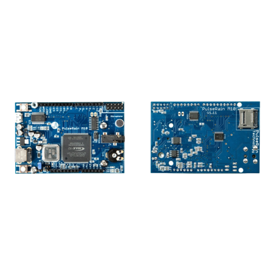
DC Jack power and the USB power are present, the power from the DC Jack will always prevail and become the active power source. 5 Major Components The M10 board has the following major components: (The packages of those components are carefully chosen to avoid BGA or QFN packages.) •... - Page 11 PulseRain M10 Board – Hardware Manual Figure 5-1 Major Components (Top Side) Figure 5-2 Major Components (Bottom Side) P a g e...
-
Page 12: Clock And Reset
96MHz. The FP51-1T processor core and peripherals are all driven by this 96MHz clock. As shown in Figure 5-1, there are two push buttons available on the M10 board. One is located close to the microUSB connector. The other is located next to the DC Jack. To follow Arduino convention, the one close to the microUSB will be used as the default reset button. -
Page 13: Usb / Uart Bridge
5.4 Voice CODEC, Onboard Microphone and Speaker Jack 5.4.1 Analog Interface The M10 board carries a voice CODEC (Si3000) from the Silicon Lab. And it has been integrated with an onboard microphone (CMC-5044PF-A) and a 3.5 mm speaker jack for analog in and out, as illustrated in Figure 5-4. -
Page 14: Digital Interface
MCLK: the master clock (4MHz), from FPGA to Si3000 • SCLK: the slave clock (2048KHz), from Si3000 to FPGA. The SCLK runs at 256 bits per frame. For M10 board, the default sample rate is set to be 8KHz, so 8KHZ * 256 = 2048KHz •... -
Page 15: Microsd
PulseRain M10 Board – Hardware Manual 5.6 microSD With a soft-core MCU, a microSD controller inside FPGA, plus a software library, the M10 board is capable of accessing the microSD card at file system level. The details of the microSD controller and the correspondent software library can be found in Ref [7]: PulseRain M10 –...
Need help?
Do you have a question about the M10 and is the answer not in the manual?
Questions and answers