Table of Contents
Advertisement
Quick Links
Advertisement
Table of Contents

Summary of Contents for Megaleds Orphos
- Page 1 INSTALLATION HANDBOOK INSTALLATION HANDBOOK REV. 02 - MAY., 2020...
- Page 2 All rights reserved. No part of this publication may be reproduced, stored in a retrieval sys- tem, or transmitted in any form or by any means, electronic, mechanical, photocopying, recording or otherwise, without the prior written permission of MEGALEDS Indústria, Comércio e Prestação de Serviços em Iluminação Ltda. (brazilian company) (MEGALEDS Industry, Commerce and Services in Ligthing Ltd.) Printed and Published in the Brazil simul-...
-
Page 3: Table Of Contents
PREPARING PROCEDURES FOR INSTALLATION: INSTALLATION PROCEDURE OF THE ORPHOS Fi8: 7.1 PROCEDURE OF THE ORPHOS WITHOUT THE EXTENSIVE BASE SET (44): 7.1.1 INSTALLATION OF C-TOOGLE NYLON ANCHOR (38): 7.1.2 INSTALLATION OF THE BOAT POWER ELECTRIC WHIP (46): 7.1.3 AMENDMENT OF THE BOAT POWER ELECTRIC WHIP (46) AND THE FEMELE CONNECTOR POWER ELECTRICH WHIP (47): 7.1.4 ASSEMBLY OF THE BRACKET BOULTED SET (35) ON THE TARGA... - Page 4 8.1.3 INSTALLATION OF THE BRACKET BOLTED SET (35): 8.1.4 CONNECTION OF THE COAXIALCABLE (50) IN THE CONECTOR (51): 8.2 PROCEDURE OF THE ORPHOS WHIT THE EXTENSIVE BASE SET (44): 8.2.1 INSTALLATION OF C-TOOGLE NYLON ANCHOR (38): 8.2.2 INSTALLATION OF THE POWER ELECTRIC WHIP (46) AND THE COXIAL CABLE (50) OF THE DIGITAL TV ANTENNA (16): 8.2.3 AMMENDIMENT OF THE BOAT POWER ELECTRIC WHIP (46)
-
Page 5: Introduction
It is a product created with innovation and design, which incorporates advanced LED (Light Emitting Diode) and fiber optic technologies. The structur- al materials used in ORPHOS are of high resistance to impacts and weathering, appropriate to the environment that is submitted. - Page 6 (starboard, port, mast, and anchor); • front-facing light; • rear-facing light; • radar reflector; • flag. OPTIONAL ACCESSORIES (*): in addition to the 8 functions of ORPHOS Fi 8, also provides: • Horn; • Digital TV antenna. ANCHOR LIGHT ALL-ROUND WHITE LIGHT RADAR REFLECTOR...
-
Page 7: Safety Recommendations
2. SAFETY RECOMMENDATIONS: Although assembly, disassembly, installation and maintenance services are simple and fast, there are safety aspects that shall be observed by the profession- als who perform such tasks. - READ CAREFULLY all safety recommendations contained in this Installation Handbook; - USE Personal Protective Equipment - PPE during all tasks performed. - Page 8 - USE Safety Belt with double Y-shaped lanyard (figure 02) for works at height, fixed with live line or in a rigid structure; - REQUEST safety guidance for this ser- vice in height by Occupational Safety profes- sionals; - READ and FOLLOW the recommenda- tions and requirements of Safety Regulations of Labor Ministry of each country;...
-
Page 9: Warranty
Lose the warranty when: • Inadequate and improper handling purposes for which the product is destined; • Any type of damage caused by fall, strike or shock in any part of ORPHOS; • Rupture of the Mast (28) caused by any type of collision, for example, during passing under the bridge, placing of cover on the boat, or other form of impact;... - Page 10 • Changes in the technical characteristics of ORPHOS, structural, electrical or any modification not authorized in writing by MEGALEDS; No included in the warranty, regular maintenance service of ORPHOS, such as adjustment, cleaning, lighting capsules, etc. Parts and components, which are replaced during the warranty period, are owned by MEGALEDS.
-
Page 11: General Description Of Orphos Line
4. GENERAL DESCRIPTION OF ORPHOS LINE: ORPHOS is an equipment developed by MEGALEDS in order to bring togeth- er in a single set all navigation lights, and the auxiliary lights for lighting the front and rear facing. In addition to these navigation devices, it can incorporate, as op- tional accessories, Digital TV Antenna and Horn. - Page 12 The Structural Set (01) consists of the Right Lateral (02) and the Left Later- al (03), according to figure 04, which are joined by their edges by Screw (04) and Locknut (05). figure 04: Structural Set - Components At the rear of the Structural Set (01) is the Back Closing (06), also made of the same material as the Laterals (02) and (03). This part is fixed by means of the Screw (07) and the Tether Bar (08) on the Laterals (02) and (03), as shown in figure 04. All these joined parts form a rigid "box" capable of receiving the other com- ponents internally and externally, having a characteristic and harmonious design. INSTALLATION HANDBOOK - NAVIGATION LIGHTS INTEGRATED SYSTEM REVISION - 02 (MAY, 2020...
- Page 13 Inside the Structural Set (01), fit the Metallic Base (09) to the Laterals (02) and (03) arranged according to figure 05, whose function is to serve as the rigid surface of the Central PCI Board (10), Mastlight Capsule Set (11) and Horn Set (12), when installed. This Metallic Base (09) is constructed of anodized aluminum sheet, which ensures corrosion resistance of this component. Still internally, there is the Radar Reflector (13) and the Fixing Support (14) of the Anchor Light Set (15).These two components are integral with each oth- er, rigidly forming a single body when joined, all of which are made of anodized aluminum plate.
- Page 14 figure 05: Internal Components INSTALLATION HANDBOOK - NAVIGATION LIGHTS INTEGRATED SYSTEM REVISION - 02 (MAY, 2020...
- Page 15 figure 06: Digital TV Antenna REVISION - 02 (MAY, 2020 INSTALLATION HANDBOOK - NAVIGATION LIGHTS INTEGRATED SYSTEM...
- Page 16 figure 07: Starboard and Port Navigation Lights In the Back Closing (06) (figure 09) there is the Rear-Facing Light Set (22) which is connected to the Central PCI Board (10) also by means of a connector proper. This set is fixed to the Back Closing (06) by the Screws (23). In case of replacement of this set, simply replace with another component of the same code.
- Page 17 In ORPHOS, the power input of the PCI Central Board (10) is made by the Male Connector (30), composed of 6 cables of different colors, duly sized to sup- port the electrical current consumption of this equipment. When assembled, ORPHOS can receive a Mast (28), made of acrylic materi- al, as high mechanical strength and weathering, as the saline environment and UV rays. This component has a fiber optic cable inside it, capable of transmitting the light from the white All-round White Light Capsule Set (11), that is, translucent, to a lens installed in the Mast Collimator Support (32) ( figure 10A).
- Page 18 09: Rear-Facing Light Set For a simple fitting the Mast (28) can be easily installed or removed, as illus- trated in figures 01 and 10B, the rear of the Structural Set (01).In turn, the Mast (28) is locked by the Mast Fixing Clamp (31) (figure 10B). The Mast (28) clamping system of the ORPHOS is simple, just position the Mast Fixing Clamp (31) with its internal pins (P), facing downwards and fit them into the side slots (Rg), as shown in figure 10B. INSTALLATION HANDBOOK - NAVIGATION LIGHTS INTEGRATED SYSTEM REVISION - 02 (MAY, 2020...
- Page 19 figure 10A: All-round White Light Capsule Set (11) Set REVISION - 02 (MAY, 2020 INSTALLATION HANDBOOK - NAVIGATION LIGHTS INTEGRATED SYSTEM...
- Page 20 To mount the Mast (28) in its correct location, position the recess (Rb) from its lower edge to downward, parallel to the ledge (Rs) of the lower rear hole(Fu 2) of the Structural Set (01). After, insert it through the upper rear hole (Fu 1), through the hole (Fu 2) until it reaches ( to stop) the Mastlight Capsule Set (11).(figure 10A). When the Mast (28) is inserted into the holes (Fu 1) and (Fu 2), until it touches the Mastlight Set (11), turn clockwise, ¼ turn the Mast Fixing Clamp (31) to lock the Mast (28) in its correct position. To remove the Mast (28), turn the Mast Fixing Clamp (31) ¼ turn again, but counterclockwise, and then pull it upwards.
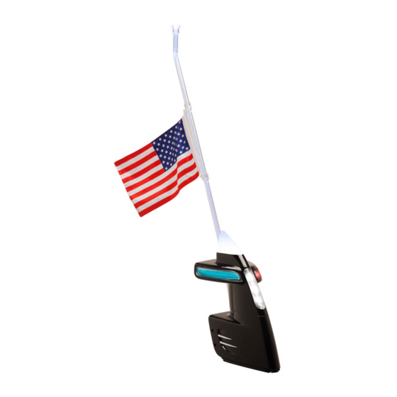
- Page 21 LOCK figure 10C: Lock System of the Mast (28) Another purpose of the Mast (28) is to serve as the point of attachment of the Flag (33).This fixing is performed by the Flag Clip (34). The complete ORPHOS described above is fitted directly into the Bracket Bolted Set (35). The Bracket Bolted Set (35), is composed of: by Bracket Base (36), produced in the same material as the Laterals (02) and (03); by Connectors Support (41); by Female Connector (40); and by Digital TV Antenna Connector - Mobile Male (51), when installed. The Bracket Base (36) is the element, which is attached to the tar- ga of the boat by means of 8 Screws (37) (figure 05).In this way, these Screws (37) are threaded directly onto C-Toogle Nylon Anchor (38), embedded in the targa of the boat.
- Page 22 Support (41), and this fixed on the Bracket Base (36) by the Screws (43) (figure 13). Depending on the dimensions and characteristics of the boat, there may be a need to install the Extensive Base Set (44) between the targa and the Bracket Bolted Set (35), whose function is to raise the height of the ORPHOS. The figure 15 shows this assembly. The Chapter 9: ELECTRICAL INSTALLATION addresses the recommenda- tions of the electrical system.
- Page 23 11: Bracket Bolted Set (35) connected to Structural Set (01) of the ORPHOS figure 12: Locking System REVISION - 02 (MAY, 2020 INSTALLATION HANDBOOK - NAVIGATION LIGHTS INTEGRATED SYSTEM...
- Page 24 figure 13: Bracket Bolted Set (35) and Components figure 14: Mounting the Male Connector (30) with Female Connector (40) INSTALLATION HANDBOOK - NAVIGATION LIGHTS INTEGRATED SYSTEM REVISION - 02 (MAY, 2020...
- Page 25 figure 15: Extensive Base (44) REVISION - 02 (MAY, 2020 INSTALLATION HANDBOOK - NAVIGATION LIGHTS INTEGRATED SYSTEM...
-
Page 26: Technical Data And Conformity
5. TECHNICAL DATA AND CONFORMITY: 5.1 TECHNICAL CHARACTERISTICS: The ORPHOS Set is composed of several components as described in the previous Chapter. In the TABLE 01 below follow the specifications of each component. TABLE 01: TECHNICAL SPECIFICATIONS of LED that make up the ORPHOS: Power: Current: Voltage:... - Page 27 31 ¾ (1806) 53 (1346) 18 ¾ (475) 9 ⅞ (250) 18 ¾ (475) BASIC DIMENSIONS: inch (mm) REVISION - 02 (MAY, 2020 INSTALLATION HANDBOOK - NAVIGATION LIGHTS INTEGRATED SYSTEM...
- Page 28 TABLE 04: COMPONENTS DESCRIBED IN THIS INSTALLATION HANDBOOK: ITEM DESCRIPTION STRUCTURAL SET RIGHT LATERAL LEFT LATERAL FIXING SCREW OF LATERAL LOCKNUT BACK CLOSING FIXING SCREW OF TETHER BAR TETHER BAR METALLIC BASE BOARD ALL-ROUND WHITE LIGHT CAPSULE SET HORN SET RADAR REFLECTOR FIXING SUPPORT ANCHOR LIGHT SET DIGITAL TV ANTENNA DIGITAL TV ANTENNA CONNECTOR - FIXED FEMALE (LEFT LATERAL) STARBOARD LIGHT SET (GREEN)
- Page 29 TABLE 04: COMPONENTS DESCRIBED IN THIS INSTALLATION HANDBOOK: (Continuation): ITEM DESCRIPTION MAST COLLIMATOR SUPPORT FLAG FLAG CLIP BRACKET BOLTED SET BRACKET BASE FIXING BOLT OF BRACKET BOLTED SET C-TOOGLE NYLON ANCHOR LEVER FEMALE CONNECTOR CONNECTOR SUPPORT FIXING SCREW FEMALE CONNECTOR FIXING SCREW EXTENSIVE BASE SET GUIDE BUSHING BOAT POWER ELECTRIC WHIP FEMALE CONNECTOR POWER ELECTRIC WHIP AMENDED POWER ELECTRIC WHIP FIXING BOLT OF EXTENSIVE BASE COAXIAL CABLE DIGITAL TV ANTENNA CONNECTOR - MOBILE MALE (BASE SET) UPPER FIXING TERMINAL OF MOBILE CONNECTOR...
-
Page 30: Certification Of Conformity
5.2 CERTIFICATION OF CONFORMITY: INSTALLATION HANDBOOK - NAVIGATION LIGHTS INTEGRATED SYSTEM REVISION - 02 (MAY, 2020... - Page 31 REVISION - 02 (MAY, 2020 INSTALLATION HANDBOOK - NAVIGATION LIGHTS INTEGRATED SYSTEM...
- Page 32 INSTALLATION HANDBOOK - NAVIGATION LIGHTS INTEGRATED SYSTEM REVISION - 02 (MAY, 2020...
-
Page 33: Preparing Procedures For Installation
6. PREPARING PROCEDURES FOR INSTALLATION: To install the ORPHOS it is necessary to take some initial steps. PROCEDURE: If the boat is on a wagon: POSITION the boat in one place: Covered; With height more than 6.5 ft (2 m) above the targa;and Safe. PROVIDE means of access to targa or the top of the roof, such as stairs, platforms, and other suitable and safe devices;... - Page 34 - 12 inches (300 mm) caliper; - clean cloth for cleaning; - pencil or fine point pen. 5. CHECK if all components are present in the ORPHOS installation kit. If any item(s) is (are) missing, PROVIDE this (these) component(s) with the MEGALEDS distributor NOT proceed in any task without the set of components being complete.
-
Page 35: Installation Procedure Of The Orphos Fi8
7.1.1 INSTALLATION OF C-TOOGLE NYLON ANCHOR (38): PLAN all tasks of installation; DEFINE the position of the ORPHOS installation; MARK the center line L1 of the targa or the roof (top) with a pencil or fine point pen (figure 16); POSITION the longitudinal center line L2 of the Bracket Bolted Set (35) on the center line of the targa, according to figure 16;... - Page 36 center line L2 cenetr line L1 figure 16: Definition of the CENTER LINE on the targa Central hole B figure17: Definition of Bracket Bolted Set (35) position INSTALLATION HANDBOOK - NAVIGATION LIGHTS INTEGRATED SYSTEM REVISION - 02 (MAY, 2020...
- Page 37 DRILL all 9 marked points on the targa or the top of the roof (figure 19); ADHESIVE DRILLING TEMPLATE (25) for mounting the ORPHOS WITHOUT Extensive Base Set (44) punch tool; figure18: Marking the 9 points on the targa or the top of the roof of the boat...
- Page 38 figure19: Drilling and Enlarging of the 9 points on the targa or the top of the boat ENLARGE the 8 holes with drill Ø 1/2 inch or Ø 13 mm; ENLARGE the central hole C1 with hole saw of Ø 1 inch or Ø 25 mm; REMOVE the Adhesive Drilling Template (25); REMOVE the burrs with a round file and sandpaper from the holes; 15. CLEAN the surface of the targa, removing dust and chips;...
- Page 39 BEND the metallic part over the strips (figure 20A); INSERT the set in one of the holes Ø ½ inch (Ø 13mm), according to figure 20A; APPLY in the hole Ø ½ inch (or Ø 13 mm) white or black figure 20B Sealing and positioning of the Silicone Sealant to seal the Guide Guide Bushing (45) Bushing (45) on the targa or the...
-
Page 40: Installation Of The Boat Power Electric Whip (46)
7.1.2 INSTALLATION OF THE BOAT POWER ELECTRIC WHIP (46): CONDUCT the Power Electric Whip (6 cables) (46) from Cabin Com- mand Panel (See Chapter 9 - ELECTRIC SYSTEM) through the interior of the targa or the top of the roof until it reaches the hole of Ø 1 inch (Ø 25 mm) from the inter- nal side; 1.3 ft (40 cm) figure 21: Positioning of the Boat Power Electric Whip (46) on the targa PASS the Power Electric Whip by hole of Ø 1 inch (Ø 25 mm) from the internal to the external side of the targa of the boat;... -
Page 41: And The Femele Connector Power Electrich Whip (47)
Silicone Sealant Silicone Sealant the targa or the top of the boat figure 22: Sealing the Guide Bushing (45) and the hole Ø ½ inch (or 13 mm) on the targa. 7.1.3 AMENDMENT OF THE BOAT POWER ELECTRIC WHIP (46) AND THE FEMALE CONNECTOR POWER ELECTRIC WHIP (47): ATTENTION! The Female Connector (40) (figure 13) has an Power Electric Whip (47) already installed, ie, each cable is connected to its... - Page 42 STRIP OFF 2 inches (50 mm) the ends of each cable of the Power Electric Whip (6 cables) (47) from the Female Connector (40). TWIST each end to increase stiffness; CUT 6 pieces of heat shrink tubing cables (thermal-retractable) with a length of 4 inches (10 cm); PLACE the piece of heat shrink tubing cables (thermal-retractable) in each cable; AMEND the ends of each cable of the two Electric Power Whip (46) and (47), according to the 5 STEPS of figure 24A, considering the colors and functions of each cable, respectively.
- Page 43 figure 23: Disposition of Bracket Bolted Set (35) from factory STAGE 1: Approach and cross the stripped off ends of the cables STAGE 2: Join and twist both ends STAGE 3: Wrap the ends STAGE 4: Weld wild soldering wire on the amendment STAGE 5: Apply the heat shrink tubing cables (thermal-retractable) on the amendment figure 24A: AMENDMENT sequence of the cable REVISION - 02 (MAY, 2020 INSTALLATION HANDBOOK - NAVIGATION LIGHTS INTEGRATED SYSTEM...
- Page 44 HEAT each heat shrink tubing cables (thermal-retractable) with Thermal Blower, until it is properly contracted over the amendment of each cable; TIE both of the Power Electric Whip (46) (47), close to each side of the amendment with nylon ty-raps for better attachment (figure 24B). targa or top of the boat Tiraps of nylon Tiraps of nylon OBSERVATION: After the Boat Power Electric Whip(46) has been amended with the Female Con- nector Power Electric Whip (47), both are transformed into the Amended Power Electric Whip (48).
-
Page 45: Assembly Of The Bracket Boulted Set (35) On The Targa
7.1.4 ASSEMBLY OF THE BRACKET BOLTED SET (35) ON THE TAR- GA OR TOP OF THE BOAT: CONDUCT the Amended Power Electric Whip (48) (figure 24B) to the interior of the targa or the op of the boat by hole of Ø 1 inch (Ø 25 mm) to enable the attachment of the Bracket Bolted Set (35); Silicone Sealant 35 or 44 37 - slotted or phillips screw Ø ¼ inch x 2 ½ inches 49 - slotted or phillips screw Ø ¼ inch x 1 inch targa or top of the boat Silicone Sealant figure 25: Fixation of the Bracket Bolted Set (35) or Extensive Base Set (44) on the targa or the top of the boat. - Page 46 POSITION the 8 Fixing Bolts of Bracket Bolted Set (37) (specification: slotted or Phillips bolts Ø ¼ inch x 2 ½ inches) into the 8 mm holes of the Bracket Bolted Set (35) to be screwed into the Guide Bushing (45) (figures 22 and 25); TIGHTEN all Bolts (37), according to figure 25; FIT the ORPHOS into the Bracket Bolted Set (35); CHECK if the fit is smooth, without the need for efforts for this operation. PROCEED: • If the fit between these sets is smooth, PROCEED according to item 15; • If the fit is locking or with great difficulty to move. REMOVE the ORPHOS from the Bracket Bolted Set (35) and PROCEED according item 8: REMOVE again the Bolts (37); CHECK the height of the gaps or chinks between the Bracket Bolted Set (35) and the targa´s surface or the top of the boat;...
- Page 47 Bracket Bolted Set (35), that is, in the passage of the Female Connector Power Electric Whip (47) (inside the Extensive Base (44), for seal this passage as the water inlet (figure 26); FIT the ORPHOS into the Bracket Bolted Set (35) definitely (figure 27); APPLY WHITE or BLACK Silicone Sealant in the hole of the Amended Power Electric Whip (48)
-
Page 48: Procedure Of The Orphos Whit The Extensive Base Set (44)
27: ORPHOS mounted on the Bracket Bolted Set (35) on the targa or the top of the boat 7.2 PROCEDURE TO ORPHOS WITH THE EXTENSIVE BASE SET (44): 7.2.1 INSTALLATION OF C-TOOGLE NYLON ANCHOR (38): PLAN all tasks of installation;... - Page 49 DRILL all 9 marked points on the targa or the top of the boat (figure 19); ADHESIVE DRILLING TEMPLATE (26) for mounting the ORPHOS WITH ENLARGE the 8 Extensive Base Set (44) holes with drill Ø 1/2 inch or Ø 13 mm;...
-
Page 50: Amendment Of The Boat Power Electric Whip
15. REMOVE the burrs with a round file and sandpaper from the holes; 16. CLEAN the surface of the targa, removing dust and chips. SEPARATE the 8 C-Toogle Nylon Anchors (38) of ¼ inch; BEND the metallic part over the strips (figure 20A); INSERT the set in one of the holes Ø according to ½ inch (Ø 13mm), figure 20A; 20. APPLY in the hole Ø ½ inch (or Ø 13 mm) white or black Silicone Seal- ant to seal the Guide Bushing (45) on the targa or the top of the boat (see figure 22);... -
Page 51: And The Female Connector Power Electric Whip (47)
7.2.3 AMENDMENT OF THE BOAT POWER ELECTRIC WHIP (46) AND THE FEMALE CONNECTOR POWER ELECTRIC WHIP (47): PROCEED the same instructions contained in item 7.1.3; FOLLOW to the item 7.2.4. 7.2.4 ASSEMBLY OF THE EXTENSIVE BASE (44) AND THE BRACKT BOLTED SET (35): POSITION the Bracket Bolted Set (35), on the surface of the targa or the top of the boat, according to figure 28, leaving 1.7 ft (40 cm) of the Amended... - Page 52 PASS the Bracket Bolted Set (35) by the middle of Extensive Base Set (44), according to figure 29, until this assembly completely passes; figure 29: Mounting and positioning the Exten- targa or top of sive Base Set (44) relative to the Bracket Bolt- the boat ed Set (35) POSITION the 8 Fixing Bolts (49) of Extensive Base Set (44) (specifica- tion: slotted or Phillips bolts Ø ¼ inch x 1inch) (figure 30B) through the inner holes (Ø 8 mm) of the lower surface of the Extension Base Set (44), to be screwed into the Guide Bushings (45) (figure 22 and 25);...
- Page 53 (*) APPLY WHITE or BLACK Silicone Sealant in the hole of the Amended Power Electric Whip (48) figure 30A: Sealant point application REVISION - 02 (MAY, 2020 INSTALLATION HANDBOOK - NAVIGATION LIGHTS INTEGRATED SYSTEM...
- Page 54 Base Set (44), that is, whether it is in line with the longitudinal line of the boat. If the alignment is NOT in accordance with plan, DISMOUNT and CORRECT the as- sembly, before to apply the Silicone Sealant. FIT the ORPHOS into the Bracket Bolted Set (35) definitely (figure 31); INSTALLATION HANDBOOK - NAVIGATION LIGHTS INTEGRATED SYSTEM REVISION - 02 (MAY, 2020...
- Page 55 31: Assembly of ORPHOS on the Extensive Base Set (44) REVISION - 02 (MAY, 2020 INSTALLATION HANDBOOK - NAVIGATION LIGHTS INTEGRATED SYSTEM...
-
Page 56: Installation Of The Coaxial Cable To The Digital Tv Antenna
8.1.1 INSTALLATION OF C-TOOGLE NYLON ANCHOR (38): FOLLOW the instructions contained in item 7.1.1 of Chapter 7 - INSTALLATION PROCEDURE OF ORPHOS Fi8 this Installation Handbook. 8.1.2 INSTALLATION OF THE POWER ELECTRIC WHIP (46) AND THE COAXIAL CABLE (50) OF THE DIGITAL TV ANTENNA (16): FOLLOW the instructions contained in item 7.1.2 of Chapter 7 -... - Page 57 1.7 ft (40 cm) figure 31: Positioning of the oat Power Electric Whip (46) and Coaxial Cable (50) on the targa or the top of the boat (inch) figure 32: Detail of the coaxial cable pickling process (50) REVISION - 02 (MAY, 2020 INSTALLATION HANDBOOK - NAVIGATION LIGHTS INTEGRATED SYSTEM...
-
Page 58: Installation Of The Bracket Bolted Set (35)
INSTALLATION OF THE BRACKET BOLTED SET (35): FOLLOW the instructions contained in items 7.1.3 of the Chapter 7 - INSTALLATION PROCEDURE OF ORPHOS Fi8 this Installation Handbook, to perform the amendment of the Power Electric Whips (46) and (47); FOLLOW the instructions contained in items 7.1.4 of the Chapter 7 -... -
Page 59: Connection Of The Coaxialcable (50) In The Conector (51)
figure 33: Disposition of Female Connector Power Electric Whip (48) and Coaxial Cable (50) 8.1.4 CONNECTION OF THE COAXIAL CABLE (50) IN THE CONNECTOR (51): CONNECT the end R (rigid cable) of the Coaxial Cable (50) in the Ter- minal (52B) (lower) by Fixing Terminal Screw (53) of the Connector (51), tightening it firmly. VERIFY the tightening of the Fixing Terminal Screw (53) (figure 34); CONNECT the end the Mesh S of the Coaxial Cable (50) in the Termi- nal (52A) upper by Fixing Terminal Screw (53) of the Connector (51), tightening it firmly. VERIFY the tightening of the Fixing Terminal Screw (53) (figure 34); APPLY on the Terminals (52A) (52B) liquid electrical tape (black color) to isolate and protect the connection if the Coaxial Cable (50) to the Connector (51); REVISION - 02 (MAY, 2020 INSTALLATION HANDBOOK - NAVIGATION LIGHTS INTEGRATED SYSTEM... -
Page 60: Procedure Of The Orphos Whit The Extensive Base Set (44)
8.2.1 INSTALLATION OF C-TOOGLE NYLON ANCHOR (38): FOLLOW the instructions contained in item 7.2.1 of Chapter 7 - INSTALLATION PROCEDURE OF ORPHOS Fi8 this Installation Handbook. 8.2.2 INSTALLATION OF THE POWER ELECTRIC WHIP (46) AND THE COAXIAL CABLE (50) OF THE DIGITAL TV ANTENNA (16):... - Page 61 APPLY liquid electrical tape (black color) figure 34: Connection of the Coaxial Cable in the Connetor (51) REVISION - 02 (MAY, 2020 INSTALLATION HANDBOOK - NAVIGATION LIGHTS INTEGRATED SYSTEM...
- Page 62 APPLY WHITE or BLACK Silicone Sealant in the hole of the Amended Power Electric Whip (48) figure 35: Sealant point application INSTALLATION HANDBOOK - NAVIGATION LIGHTS INTEGRATED SYSTEM REVISION - 02 (MAY, 2020...
-
Page 63: And The Female Connector Power Electric Whip (47)
ASSEMBLY OF THE EXTENSIVE BASE (44) AND THE BRACKET BOLTED SET (35): FOLLOW the instructions contained in item 7.2.4 of Chapter 7 - INSTALLATION PROCEDURE OF ORPHOS Fi8 this Installation Handbook; FOLLOW to the item 8.2.5. 8.2.5 CONNECTION OF THE COAXIAL CABLE (50) IN THE CONNEC- TOR (51): FOLLOW the instructions contained in item 8.1.4 of Chapter 7 -... -
Page 64: Final Procedure After The Assembly Of The Orphos
8.3 FINAL PROCEDURE AFTER THE ASSEMBLY OF THE ORPHOS: CLEAN the targa surface or the top of the boat with a clean, damp cloth; PERFORM operating tests of the Navigation Lights (11) (18) (19) and the Front-Facing Light (21), Rear-Facing (22), and Anchor Light (15); APPROVE the installation by a legally qualified professional (naval engineer and / or electrical engineer). -
Page 65: Electric System
9. ELECTRIC SYSTEM The ORPHOS electrical installation on the boat shall be preceded by some precautions to avoid any damage to the equipment. The following are RECOMMENDATIONS for installation, in order to assist the installation professionals, to perform the correct assembly of ORPHOS. It is RESPONSIBILITY of the installer: • the manufacture of the Boat Power Electric Whip (46); • the definition, purchase and installation of the switches of the navigation lights and facing lights, in addition to the horn, where applicable;... - Page 66 TABLE 06: FLEXIBLE ELECTRIC CABLE SPECIFICATION Specification Flexible Cable 0,6/1kV HEPR 90 For power distribution and distribution circuits in underground net- works that require cables with greater flexibility to be installed in conduits, with self-extinguishing characteristics of the fire, greater Application: safety, isolated in HEPR (ethylene-propylene rubber) with operating temperature of 90ºC, and capacity electrical current higher than PVC insulated cables. Electrolytic copper wires, soft tempering, class 4 stranding to the nominal section of 6mm² and class 5 stranding from section Conductor 10mm² (extra-flexible) complying with the specification technical...
- Page 67 APPLY liquid electrical tape in all connections of the Switches termi- nals, Circuit Breakers and Fuses, when connected by terminals and fixed by screws; FOLLOW the ELECTRICAL DIAGRAM as RECOMMENDATION; REQUEST the supervision of a professional qualified and authorized by the owner of the boat or the yard to attest to the quality of the complete ORPHOS installation on the boat; 10. EXECUTE all installation service only by qualified, authorized and trained technicians at ORPHOS.
- Page 68 INSTALLATION HANDBOOK - NAVIGATION LIGHTS INTEGRATED SYSTEM REVISION - 02 (MAY, 2020...
-
Page 69: Trouble Shooting
10. TROUBLE SHOOTING: The TABLE as following describe the means PROBLEMS, CAUSES and which may arise during or the end the assembly of ORPHOS. SOLUTIONS If doubt, or problems that are not described below, CONSULT the Technical Sup- port of the MEGALEDS. - Page 70 4. The Central PCI Board (10) is dam- 4. REPLACE the Central PCI Board aged or correspondent cable (RED) is (10), however CONSULT the Technical disconnected or damaged. Support MEGALEDS. 5. REPLACE F4 Fuse (5A) and VERIFY 5. F4 Fuse (5A) burnt the cause of occurrence. If necessary, CONSULT Technical Support. 1. REPLACE the capsule, however 1. The correspondent Navigation Light CONSULT the Technical Support ME- Capsule is damaged.
- Page 71 Lights does navigation light that does not light up again, however CONSULT the Techni- is damaged, broken or disconnected. not light up cal Support MEGALEDS. (continuation) 1. REPLACE the Anchor Light Set 1. The correspondent Anchor Light (15), however CONSULT the Technical Capsule is damaged.
- Page 72 (continuation) 1. REPLACE the Front-Facing Light 1. The capsules of the Front-Facing Set (21), however CONSULT the Tech- Light are damaged. nical Support MEGALEDS. 2. The Central PCI Board (10) is dam- 2. REPLACE the Central PCI Board aged or correspondent cable (WHITE) (10), however CONSULT the Technical is disconnected or damaged.
- Page 73 (continuation) 1. REPLACE the Rear-Facing Light Set 1. The capsules of the Rear-Facing (22), however CONSULT the Technical Light are damaged. Support MEGALEDS. 2. The Central PCI Board (10) is dam- 2. REPLACE the Central PCI Board aged or correspondent cable (BLUE) (10), however CONSULT the Technical is disconnected or damaged.
- Page 74 4. There is oxidation between the 4. CLEAN the contacts of Connectors Connectors (17) and (51) when the (17) and (51), and VERIFY the signal ORPHOS is attached with Bracket of Digital TV. Bolted Set (35). 5. One of Connectors (17) or (51) are 5. REPAIR the fixation of Connectors loose, do not allow the contact be- (17) or (51). CONSULT Technical Sup-...
- Page 75 1. The Horn Set (12) is damaged. VERIFY Chapter 11 - SPARE PARTS or CONSULT the Technical Support MEGALEDS. 2. The SA1 Push Button is damaged 2. INSPECT and REPLACE the SA1 or disconnected from the Boat Power Push Button or CONNECT the corre- Electric Whip (46).
- Page 76 Bracket CONSULT Technical Support Bolted Set 2. The Back Closing (06) has suffered MEGALEDS. It is recommended EXE- (35) some damage, and presents cracks, CUTE this replacement operation by rupture of pieces, etc.. Technical Support MEGALEDS. 10. Infiltration 1. Missing seal between Bracket Bolt- 1. REMAKE the silicone sealant seal,...
-
Page 77: Spare Parts
11. SPARE PARTS: The ORPHOS Set is composed of several components, some of which can be replaced as SPARE PARTS in case of maintenance and repair. For purchase of SPARE PARTS or REPLACEMENT SET, PROCEED: OBSERVE the figure 30, as follow; CHOOSE the part or set necessary; NOTE the ML CODE (2 column) of TABLE 07 of necessary(ies) part(s) or set(s); FILL the PURCHASE ORDER with the request data;... - Page 78 figure 30 INSTALLATION HANDBOOK - NAVIGATION LIGHTS INTEGRATED SYSTEM REVISION - 02 (MAY, 2020...
- Page 79 TABLE 07: REPLACEMENT SETS OR SPARE PARTS: POS. CODE PART NUMBER QTD. ML-2-0039-4 REAR FACING LIGHT SET ML-2-0043-9 LEVER ML-2-0037-2 ANCHOR LIGHT SET ML-2-0027-6 FRONT FACING LIGHT SET ML-2-0045-1 USA FLAG SET ML-2-0055-2 BRAZILIAN FLAG SET ML-2-0047-3 FLAG MAST SET ML-2-0023-7 FEMALE CONNECTOR SET ML-2-0049-5 COLLIMATOR LENS SET ML-2-0041-7 ALL-ROUND WHITE LIGHT SET ML-2-0031-6 STARBOARD LIGHT SET ML-2-0033-8 PORT LIGHT SET ML-2-0025-9 HORN SET...
- Page 80 REAR FACING LIGHT SET: CODE ML-2-0039-4 POS. CODE PART Nº QTD. ML-1-0077-5 REAR-FACING LIGHT ML-1-0079-7 PA-AA-PH M2,9x9,9 INSTALLATION HANDBOOK - NAVIGATION LIGHTS INTEGRATED SYSTEM REVISION - 02 (MAY, 2020...
- Page 81 LEVER SET: CODE ML-2-0043-9 Nº DO ITEM Nº DA PEÇA QTD. Capsula luz de popa (ML-1-0201-4) ML-1-0079-7 PA-AA-PH M2,9x9,5 POS. CODE PART Nº QTD. ML-1-0111-4 LEVER R7 ML-1-0113-6 SHAFT R7 ML-1-0115-8 SPRING R7 ML-1-0117-0 ELASTIC RING D4 REVISION - 02 (MAY, 2020 INSTALLATION HANDBOOK - NAVIGATION LIGHTS INTEGRATED SYSTEM...
- Page 82 ANCHOR LIGHT SET: CODE ML-2-0037-2 POS. CODE PART Nº QTD. ML-1-0081-0 ANCHOR LIGHT ML-1-0083-2 PA-AA-PH M2,9x13 INSTALLATION HANDBOOK - NAVIGATION LIGHTS INTEGRATED SYSTEM REVISION - 02 (MAY, 2020...
- Page 83 FRONT FACING LIGHT SET: CODE ML-2-0027-1 POS. CODE PART Nº QTD. ML-1-0085-4 FRONT FACING LIGHT LENS ML-1-0087-6 LIGHT ML-1-0089-8 LIGHT PLATE ML-1-0093-3 PA-AA-PN-PH M2,9x9,0 ML-1-0091-1 PA-AA-PN-PH M2,9x22 REVISION - 02 (MAY, 2020 INSTALLATION HANDBOOK - NAVIGATION LIGHTS INTEGRATED SYSTEM...
- Page 84 USA FLAG SET: CODE ML-2-0045-1 POS. CODE PART Nº QTD. ML-1-0151-8 FLAG CLIP ML-1-0147-3 USA FLAG ML-1-0151-8 TY-RAP - ZIP TIES INSTALLATION HANDBOOK - NAVIGATION LIGHTS INTEGRATED SYSTEM REVISION - 02 (MAY, 2020...
- Page 85 BRAZILIAN FLAG SET: CODE ML-2-0055-2 POS. CODE PART Nº QTD. ML-1-0215-9 FLAG CLIP ML-1-0149-5 BRAZILIAN FLAG ML-1-0151-8 TY-RAP - ZIP TIES REVISION - 02 (MAY, 2020 INSTALLATION HANDBOOK - NAVIGATION LIGHTS INTEGRATED SYSTEM...
- Page 86 FLAG MAST SET: CODE ML-2-0047-3 POS. CODE PART Nº QTD. ML-1-0155-2 MAST FIXING CLAMP ML-1-0153-0 FLAG MAST INSTALLATION HANDBOOK - NAVIGATION LIGHTS INTEGRATED SYSTEM REVISION - 02 (MAY, 2020...
- Page 87 FEMALE CONNECTOR SET: CODE ML-2-0023-7 POS. CODE PART Nº QTD. ML-1-0103-5 FEMALE PLUG ML-1-0105-7 CONNECTOR WASH ML-1-0107-9 PA-MQ-PN-PH MA 3X12 ML-1-0075-3 LOCKNUT M3 REVISION - 02 (MAY, 2020 INSTALLATION HANDBOOK - NAVIGATION LIGHTS INTEGRATED SYSTEM...
- Page 88 COLLIMATOR LENS SET: CODE ML-2-0049-5 POS. CODE PART Nº QTD. ML-1-0275-5 COLLIMATOR SUPPORT ML-1-0277-7 COLLIMATOR SUPPORT COVER ML-1-0095-5 COLLIMATOR CA15902 ML-1-0099-9 PA-AA-PN-PH M2,9x6,5 INSTALLATION HANDBOOK - NAVIGATION LIGHTS INTEGRATED SYSTEM REVISION - 02 (MAY, 2020...
- Page 89 ALL-ROUND WHITE LIGHT SET: CODE ML-2-0041-7 POS. CODE PART Nº QTD. ML-1-0119-2 ALL-ROUND WHITE LIGHT CAPSULE ML-1-0121-5 PA-AA-PN-PH M2,9x9,5 REVISION - 02 (MAY, 2020 INSTALLATION HANDBOOK - NAVIGATION LIGHTS INTEGRATED SYSTEM...
- Page 90 STARBOARD LIGHT SET: CODE ML-2-0031-6 POS. CODE PART Nº QTD. ML-1-0127-1 STARBOARD LIGHT ML-1-0083-2 PA-AA-PN-PH M2,6x13 INSTALLATION HANDBOOK - NAVIGATION LIGHTS INTEGRATED SYSTEM REVISION - 02 (MAY, 2020...
- Page 91 PORT LIGHT SET: CODE ML-2-0033-8 POS. CODE PART Nº QTD. ML-1-0123-7 PORT LIGHT ML-1-0083-2 PA-AA-PN-PH M2,6x13 REVISION - 02 (MAY, 2020 INSTALLATION HANDBOOK - NAVIGATION LIGHTS INTEGRATED SYSTEM...
- Page 92 HORN SET: CODE ML-2-0025-9 POS. CODE PART Nº QTD. ML-1-0129-3 HORN ML-1-0131-6 AR-LI-INOX 304 1/4 POL ML-1-0133-8 PO-NY-INOX 394 BX6 CHV 10 POL INSTALLATION HANDBOOK - NAVIGATION LIGHTS INTEGRATED SYSTEM REVISION - 02 (MAY, 2020...
- Page 93 ANTENNA CONNECTOR SET:w CODE ML-2-0029-3 POS. CODE PART Nº QTD. ML-1-0141-7 ANTENNA CONNECTOR ML-1-0143-9 ANTENNA ML-1-0145-1 PA-CH-PH-AA INOX 304 3,5x13 ML-1-0107-9 PA-MQ-PN-PH-MA 3x12 ML-1-0109-1 NUTLOCK M3 REVISION - 02 (MAY, 2020 INSTALLATION HANDBOOK - NAVIGATION LIGHTS INTEGRATED SYSTEM...
- Page 94 CENTRAL PCI BOARD SET: CODE ML-2-0035-0 POS. CODE PART Nº QTD. ML-1-0135-0 CENTRAL BOARD ML-1-0137-2 MALE CONNECTOR ML-1-0105-7 CONNECTOR WASH ML-1-0139-4 PA-A-A-PN-PH M2,9x9,5 INSTALLATION HANDBOOK - NAVIGATION LIGHTS INTEGRATED SYSTEM REVISION - 02 (MAY, 2020...
-
Page 95: Note
NOTE: REVISION - 02 (MAY, 2020 INSTALLATION HANDBOOK - NAVIGATION LIGHTS INTEGRATED SYSTEM... - Page 96 NOTE: INSTALLATION HANDBOOK - NAVIGATION LIGHTS INTEGRATED SYSTEM REVISION - 02 (MAY, 2020...
- Page 97 NOTE: REVISION - 02 (MAY, 2020 INSTALLATION HANDBOOK - NAVIGATION LIGHTS INTEGRATED SYSTEM...
- Page 98 INSTALLATION HANDBOOK - NAVIGATION LIGHTS INTEGRATED SYSTEM REVISION - 02 (MAY, 2020...
- Page 100 www.megaleds.com.br...
Need help?
Do you have a question about the Orphos and is the answer not in the manual?
Questions and answers