
Subscribe to Our Youtube Channel
Related Manuals for NINGBO DAVID 90 Series

Summary of Contents for NINGBO DAVID 90 Series
- Page 1 EDITION/REVISION B/0 NINGBO DAVID SERVICE MANUAL YP-90 YP-90A YP-90B YP-90 AB 90 SERIES INFANT INCUBATOR...
- Page 2 NINGBO DAVID MEDICAL DEVICE CO., LTD. ADD: NO.158 DAQING ROAD, SHIPU, NINGBO, ZHEJIANG PROVINCE, CHINA POST CODE: 315731 FAX: 0086-574-65962111 MARKETING CENTER: NO. 100, JINGHUA ROAD, HI-TECH INDUSTRIAL DEVELOPMENT ZONE, NINGBO, CHINA POST CODE: 315000 TEL: 0086-574-87800008, 87800009 FAX: 0086-574-87801111 E-MAIL: sales@chinadavid.cn...
- Page 3 SERVICE MANUAL FOR INFANT INCUBATOR EDITION/REVISION B/0 WARRANTY The product being described in this manual is warranted against defects in materials or workmanship for one year from the date of shipment, with the following exceptions. 1. All consumable and disposable products are guaranteed to be free from defects upon shipment only.
- Page 4 SERVICE MANUAL FOR INFANT INCUBATOR EDITION/REVISION B/0 COMPLEMENTARY NOTICE Since our company, conducts a continuous product improvement program, circuit and component improvements are sometimes incorporated into equipment before they can be incorporated into the printed manuals. This manual contains proprietary information, repairs and authorized modifications should be performed only by qualified service personnel to maintain your warranty and to avoid creating safety hazards.
- Page 5 SERVICE MANUAL FOR INFANT INCUBATOR EDITION/REVISION B/0 TEMPERATURE VARIABILITY: The variability of the Incubator Temperature that will be observed over a one hour period after Incubator Temperature Equilibrium has been reached. TEMPERATURE RISING TIME: The time required for the Incubator Temperature to rise 11℃, when the Air Control Temperature is at least 12℃...
- Page 6 SERVICE MANUAL FOR INFANT INCUBATOR EDITION/REVISION B/0 SYMBOLS Attention, Consult Accompanying Documents. Class I Equipment Type BF Applied Part CLASS I (Connection to the mains) (Disconnection to the mains) (Only For A Part Of Equipment) (Only For A Part Of Equipment) AC Power 220-230V, 50Hz RS-232 220-230V~/50Hz...
- Page 7 SERVICE MANUAL FOR INFANT INCUBATOR EDITION/REVISION B/0 SEASONAL SAFETY CHECK 1. Please clean the plug of power cord at least once a year. Too much dust on plug may cause the fire. 2. The following safety checks should be performed at least every 12 months by a qualified person who has adequate training, knowledge, and practical experience to perform these tests.
- Page 8 SERVICE MANUAL FOR INFANT INCUBATOR EDITION/REVISION B/0 TABLE OF CONTENTS SECTION PAGE 1. GENERAL INFORMATION…………………………………………………………………………………1-1 1.1 INTRODUCTION……………………………………………………………………………………………1-1 1.2 DESCRIPTION……………………………………………………………………………………………1-1 1.3 ACCESSORIES……………………………………………………………………………………………1-1 2. INSTALLATION………………………………………………………………………………………………2-1 2.1 UNPACKING………………………………………………………………………………………………2-1 2.2 ASSEMBLING ………………………………………………………………………………………………2-1 2.3 OPERTION CHECKOUT PROCEDURES ………………………………………………………………2-6 3.TECHNICAL INFORMATION………………………………………………………………………………3-1 3.1 SPECIFICATION……………………………………………………………………………………………3-1 3.2 WORKING PRINCIPLE……………………………………………………………………………………3-3 4.
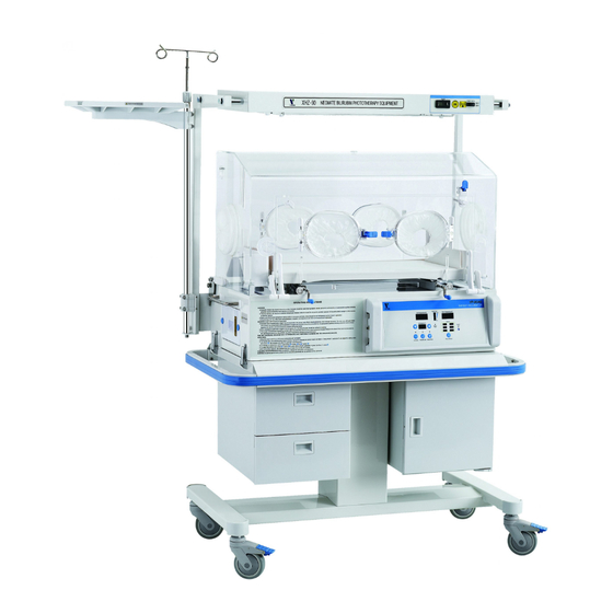
- Page 9 SERVICE MANUAL FOR INFANT INCUBATOR EDITION/REVISION B/0 SECTION 1 GENERAL INFORMATION 1.1 INTRODUCTION This manual provides instructions for installation, maintenance and repair the David Infant Incubators, Model YP-90,YP-90A, YP-90B, YP-90AB. Among these models, YP-90AB is with all functions other models have. This manual is intended for use only by trained, qualified service personnel.
- Page 10 SERVICE MANUAL FOR INFANT INCUBATOR EDITION/REVISION B/0 DESCRIPTION OF PART EXPLANATION A kind of bearing part, which is used for hanging the infusion bottle. I.V. Pole Max. Load: 2Kg The core part with two kinds of temperature control modes: air mode, baby mode, and the optional function :>37°Temperature Controller Override Mode, and it is used for automatic controlling of heat...
- Page 11 SERVICE MANUAL FOR INFANT INCUBATOR EDITION/REVISION B/0 SECTION 2 INSTALLATION 2.1 UNPACKING Generally, the Infant Incubator is usually packed to two cartons: main body and fixed cabinet or Vertical Height Adjustment cabinet(VHA cabinet). When taking out the equipment from the cartons, take care not to damage the spare parts of the Infant Incubator.
- Page 12 SERVICE MANUAL FOR INFANT INCUBATOR EDITION/REVISION B/0 b. Install the main body onto the fixed stand 1). See figure 2.2, lock the casters with brake, and put the main body onto the fixed, and connect it with the lock mechanism on two sides of stand. Main body of Incubator Lock mechanism Fixed Stand...
- Page 13 SERVICE MANUAL FOR INFANT INCUBATOR EDITION/REVISION B/0 B. The installation of main body onto the cabinet a. As figure 2.3 indicates, put on the spring washer, flat washer on the casters, and then connect with cabinet firmly. Note: The caster with brake must be installed in front of the cabinet. FIGURE 2.3 b.
- Page 14 SERVICE MANUAL FOR INFANT INCUBATOR EDITION/REVISION B/0 C. Install the main body onto the Vertical Height Adjustment Stand a. The method of installation casters is same as part B. b. The method of installation main body, guard rail on the Vertical Height Adjustment cabinet same as part B.
- Page 15 SERVICE MANUAL FOR INFANT INCUBATOR EDITION/REVISION B/0 Hexagon bolt Fixed seat Infusion rod Step 1: loose the hexagon bolts on the fixed seat with spanner, insert the I.V. Pole to the bottom, and fix the bolt to fasten the infusion rod. Hook For Infusion Rod Hexagon Bolt Step 2: Tight the hexagon bolts on the...
- Page 16 SERVICE MANUAL FOR INFANT INCUBATOR EDITION/REVISION B/0 2.3 OPERATION CHECKOUT PROCEDURE WARNING 1. Please stop using this model once some function lost or the spare parts for front access panel is loose. ℃ 2. set temperature must be high 3 than ambient temperature.
- Page 17 SERVICE MANUAL FOR INFANT INCUBATOR EDITION/REVISION B/0 E. CHECK THE ACCURACY OF TEMPERATURE CONTROL Select the Air Mode, and set the air temperature at 36℃, after the air temperature enters into the STEADY TEMPERATURE CONDITION, put the calibrated temperature measuring device on the position above 10cm from the center of mattress to measure the air temperature, compared with the indicated air temperature to check whether the deviation between them is within 0.8℃.
- Page 18 SERVICE MANUAL FOR INFANT INCUBATOR EDITION/REVISION B/0 H. CHECK FAN MOTOR ALARM Block the inlet port and outlet port on the left and right side of main deck, after several minutes, the device gives alarms, the “Fan” alarm light will flash with continuous audible sound, and the Set Temperature indicator will show alarm code E0.7.
- Page 19 SERVICE MANUAL FOR INFANT INCUBATOR EDITION/REVISION B/0 NOTE: If the system can not enter into the TEMPERATURE ALARM CHECKOUT STATE or the air temperature does vary within ±3℃ than the setting temperature, the deviation alarm can not occur. In Baby Mode, set the temperature at 35 ºC. Enter TEMPERATURE ALARM CHECKOUT STATE, put the skin sensor into the water cup at 37 ºC.
- Page 20 SERVICE MANUAL FOR INFANT INCUBATOR EDITION/REVISION B/0 L. CHECK FRONT ACCESS PANEL The Pawl Latch LOCKED UNLOCK Rotate the panel Latches and open the Access Pane to the full open position (rotate downward). Close the Access Panel and rotate both latches until they are fully locked. Both latches must be fully locked to avoid accidental opening of the panel.
- Page 21 SERVICE MANUAL FOR INFANT INCUBATOR EDITION/REVISION B/0 O. CHECK MATTRESS TILT MECHANISM The mattress tilt mechanism to adjust it. P. CHECK BASSINET Open the Access Panel and slide it out to the fully extended position indicated by the arrow. Lean on Mattress Tray to make sure it is properly supported to provide a firm infant platform.
- Page 22 SERVICE MANUAL FOR INFANT INCUBATOR EDITION/REVISION B/0 WARNING: A dirty Air Intake filter may affect oxygen concentration and/or cause Carbon Dioxide build-up. The filter must be checked on a routine basis and changed at least every two months. R. CHECK THE HIGHT ADJUSTMENT OF THE CABINET Step the Up and Down button with your feet to adjust the height of whole unit.
- Page 23 SERVICE MANUAL FOR INFANT INCUBATOR EDITION/REVISION B/0 SECTION 3 TECHNICAL INFORMATION 3.1 SPECIFICATION Specifications for the Incubators are provided in Table 3.1. All specifications maybe subject to change without advance notice. Open Access Doors and Front Panel or change Mattress obliquity, which can alter the air flow pattern, may affect temperature uniformity, temperature variability, the correlation of the Incubator temperature reading to center mattress temperature and infant skin temperature.
- Page 24 SERVICE MANUAL FOR INFANT INCUBATOR EDITION/REVISION B/0 TABLE 1.1 SPECIFICATIONS (continued) Deviation of air and isolated sensor failure……………………………………………Alarm code E0.3 Air flow temperature sensor failure………………………………………………………Alarm code E0.4 Skin temperature sensor failure…………………………………………………………Alarm code E0.5 Over-temp failure……………………………………………………………………………Alarm code E0.6 Air cycle failure ……………………………………………………………………………Alarm code E0.7 Wrong position of skin sensor failure……………………………………………………Alarm code E0.8 Fan motor failure……………………………………………………………………………Alarm code E0.9 High deviation alarm………………………………………………………………………Alarm code E1.0...
- Page 25 SERVICE MANUAL FOR INFANT INCUBATOR EDITION/REVISION B/0 3.2 WORKING PRINCIPLE 3.2.1 General This section contains a functional description and detailed theory of operation of the equipment. A system block diagram of the Controller is shown in Figure 3.2 and 3.3. The control of temperature is achieved by means of air circulation system as shown in Figure 3.1.
- Page 26 SERVICE MANUAL FOR INFANT INCUBATOR EDITION/REVISION B/0 Keypad control Indicator Fan motor checking I/O control Temperature heater control MAIN Air Temperature sensor Skin temperature sensor Air flow temperature sensor Isolated temperature sensor AUXILIARY Temperature heater control FIGURE 3.2 CONTROL BLOCK DIAGRAM...
- Page 27 SERVICE MANUAL FOR INFANT INCUBATOR EDITION/REVISION B/0 Start INT1 Initialization Real timer Data display Return INT0 Key input ADC Sampling Key handling Return Data handling Timer interruption Timer Trouble checking Return Alarm identification Series port interruption Heating control Data transfer Data display Return FIGURE 3.3 PROCEDURE BLOCK DIAGRAM...
- Page 28 SERVICE MANUAL FOR INFANT INCUBATOR EDITION/REVISION B/0 3.2.2 Temperature Control In baby Mode, the controller will control the incubator temperature automaticlly to keep the air temperature close to the set value. Comparing the air temperature and the air set temperature, the controller will adjust the heat output proportion to keep the heat balance inside hood.
- Page 29 SERVICE MANUAL FOR INFANT INCUBATOR EDITION/REVISION B/0 TABLE 3.2 ALARM ALARM MESSAGE DESCRIPTION If short-circuit or open-circuit or bad connection occurs on the air flow Code temperature sensor, at the same time, heater stops working, press E0.4 Silence/Reset Key to clear alarming for 4min, please refer to the service part.
- Page 30 SERVICE MANUAL FOR INFANT INCUBATOR EDITION/REVISION B/0 TABLE 3.1 ALARM (CONTINUE) ALARM MESSAGE DESCRIPTION ROM inside of main MCU fails. At this time, the heater will stop working , Code press Silence/Reset Key to clear alarming for 4min, please refer to the H0.1 service part.
- Page 31 SERVICE MANUAL FOR INFANT INCUBATOR EDITION/REVISION B/0 SECTION 4 CLEANING AND MAINTENANCE 4.1 GENERAL The section provides cleaning and maintenance instructions. WARNING 1.Disconnect all the connections with oxygen feeding device before cleaning and maintenance. Cleaning or maintenance in the environment full with oxygen will cause fire or explosion.
- Page 32 SERVICE MANUAL FOR INFANT INCUBATOR EDITION/REVISION B/0 B. Remove the bassinet See figure 4.2, Push bassinet inward and raise it as the arrow 1 indicates, and remove the bassinet as the arrow 2 indicates and remove the bed sheet. FIGURE 4.2 C.
- Page 33 SERVICE MANUAL FOR INFANT INCUBATOR EDITION/REVISION B/0 D. Remove Air Intake Tube Connector See Figure 4.4, Move the Air Intake Tube out in direction of arrow 2 after disconnecting Air Intake Tube from Air Tube Connector in direction of arrow 1 . FIGURE 4.4 E.
- Page 34 SERVICE MANUAL FOR INFANT INCUBATOR EDITION/REVISION B/0 D. Clean the controller Use detergent to clean the all surfaces thoroughly, then be especially careful when cleaning fans, heater and surface of air temperature sensor. Then dry them with clean cloth. CAUTION: Pay particular attention to avoid liquid seeping into the Controller Hood. clean the surface of controller after the heater becomes cold.
- Page 35 SERVICE MANUAL FOR INFANT INCUBATOR EDITION/REVISION B/0 I. Clean NEONATE BILIRUBIN OHOTOTHERAPY EQUIPMENT See the user’s manual for XHZ-90 and XZH-90L. J. Clean surface of device Use a disinfectant-detergent to thoroughly clean all surfaces, including all holes, indentations, Access Doors and Iris Ports then dry them with a clean cloth or paper towel. 4.2.3 REASSEMBLY AFTER CLEANING NOTE: Before reassembling parts into Incubator, check carefully if there is any crack or damage.
- Page 36 SERVICE MANUAL FOR INFANT INCUBATOR EDITION/REVISION B/0 C. Place Main Deck back and install the seal on it. WARNING: Be sure the two thumb screws that hold the bassinet are tightened. The right side and the wrong side of seal must be placed in the right position, and make sure the airproof to avoid the inepuality of heating towards the bed.
- Page 37 SERVICE MANUAL FOR INFANT INCUBATOR EDITION/REVISION B/0 Step 2: Rotate outer ring to close. If properly installed, the sleeve will open again if rotation is reversed. FIGURE 4.9 F. See figure 4.10, install the Access door gasket, and then install the Access door cuff. access door gasket, inner wall of hood, Access door wall, outside wall of hood, installation groove of Access door cuff.
- Page 38 SERVICE MANUAL FOR INFANT INCUBATOR EDITION/REVISION B/0 H. Install the Mattress cover with the mattress, and put the bassinet inside hood according to the oposite order. (see Figure 4.2) WARNING: Place the bassinet as the label indicates on the infant bed. 4.3 STERILIZATION NOTE: Please do not steam autoclave.
- Page 39 SERVICE MANUAL FOR INFANT INCUBATOR EDITION/REVISION B/0 SECTION 5 SERVICE 5.1 GENERAL This section provides system setting procedure and the troubleshooting procedure of these parts: replacement of Fuse, Internal charging Battery and Controller. 5.2 REPLACEMENT OF ELEMENT 5.2.1 REPLACEMENT OF FUSE Open Temperature Controller, replace the same type fuse with same specification accorind to the label on the circuit board.
- Page 40 SERVICE MANUAL FOR INFANT INCUBATOR EDITION/REVISION B/0 5.3 SYSTEM SETTING PROCEDURES 5.3.1 GENERAL This paragraph provides controller system setting procedure. NOTICE: Please follow by the procedures of item 5.3.3. if it is unnecessary, please do not change data of system setting to avoid hazards. 5.3.2 BRIEF INTRODUCTION Controller system setting procedures listed below: 1.
- Page 41 SERVICE MANUAL FOR INFANT INCUBATOR EDITION/REVISION B/0 5.3.3 PROCEDURE At first, connected power supply, press and hold Set key for 2s as soon as switch on until Air temprature indicator displays “ --.-“, and no display on Skin and Set temprature indicator. And then, press Up or Down until Air temprature indicator displays “78.6”, after then, press Set key to enter into the system set screen, or press Silence/Reset key to exit.
- Page 42 SERVICE MANUAL FOR INFANT INCUBATOR EDITION/REVISION B/0 CODE 00.1 LED Lightness set Indicate the lightness , and set range is 00.1~01.5. The larger the lighter. CODE 00.2 Air temperature sensor compensation Set value of temperature compensation for air temperature sensor , and set range is -5.0~05.0 , the first figure of set value means the increasing and decreasing value.
- Page 43 SERVICE MANUAL FOR INFANT INCUBATOR EDITION/REVISION B/0 CODE 01.1 Minimum set value of air temperature Set method of Minimum set value of air temperature, and set range is 20.0~34.0. For example, ℃ 25.0 means Minimum set value 25.0 CODE 01. 2 Maximum set value of air temperature Set method of Maximum set value of air temperature in mode of>37.0℃...
- Page 44 SERVICE MANUAL FOR INFANT INCUBATOR EDITION/REVISION B/0 5.4 TROUBLESHOOTING PROCEDURES 5.4.1 GENERAL Troubleshooting guides for the Controller are provided in Paragraph 5.4.3 and Paragraph 5.4.4. Paragraph 5.4.3 provides the alarm code when the controller alarms. Paragraph 5.4.4 provides troubleshooting in the form of flowcharts. It is confirmed that the system settings are correct before troubleshooting.
- Page 45 SERVICE MANUAL FOR I FANT INCUBATOR EDITION/REVISION B/0 TABLE 5.1 ERROR CODES (Continued) EXPLANATION AND ALARM CODE TYPE CORRECTIVE ACTION E0.4 Air flow sensor alarm Refer to Flow chart 5.4 E0.5 Skin temperature sensor failure alarm Refer to Flow chart 5.5 E0.6 Over temperature failure alarm Refer to Flow chart 5.6...
- Page 46 SERVICE MANUAL FOR INFANT INCUBATOR EDITION/REVISION B/0 5.4.4 TROUBLESHOOTING FLOW CHART Before troubleshooting, forst, please switch off, and disconnect the power cable, and then open the top cover of warmer module and the back cover of column. And then connect the power cable and turn onthe switch, at the same time, make sure that power +5V, +12V of controller, element, and all cables are in good condition.In working state, press Up Key and Air mode Key , you can find the isolated temperature and air flow temperarture in the air and set temperature indicator respectively.
- Page 47 SERVICE MANUAL FOR INFANT INCUBATOR EDITION/REVISION B/0 ISOLATED TEMPERATURE SENSOR FAILURE ALARM E0.2 Good conection? Check connection of isolated temperature sensor, and the wiring of all circuit board The 31.0℃±0.2℃ Air Temperature Simulation (decade Equal to 23166Ω±182Ω)is instead of the isolated temperature sensor, turn on power supply See 5.4.4, the isolated temperature is 31.0℃...
- Page 48 SERVICE MANUAL FOR INFANT INCUBATOR EDITION/REVISION B/0 Air temperature deviation failure alarm E0.3 Good conection? Check connection of isolated temperature sensor, and the wiring of all circuit board The 31.0℃±0.2℃ Air Temperature Simulation (decade Equal to 23166Ω±182Ω)is instead of the air and isolated temperature sensor, turn on power supply See 5.4.4, check whether The air temeprature and...
- Page 49 SERVICE MANUAL FOR INFANT INCUBATOR EDITION/REVISION B/0 Air flow sensor failure alarm E0.4 Good conection? Check connection of sensor,and the wiring of all circuit board The 31.0℃±0.2℃ Air Temperature Simulation (decade Equal to 23166Ω±182Ω)is instead of air flow temperature sensor, turn on power supply See 5.4.4, check whether The air temeprature and isolated tempertire is...
- Page 50 SERVICE MANUAL FOR INFANT INCUBATOR EDITION/REVISION B/0 SKIN TEMPERATURE SENSOR FAILURE ALARM E0.5 Check connection between skin sensor Good conection? Socket and circuit board, the connection Of all circuit board The 31.0℃±0.2℃ Air Temperature Simulation (decade Equal to 23166Ω±182Ω)is instead of air flow temperature sensor, turn on power supply the temperature display is 31.0℃, added...
- Page 51 SERVICE MANUAL FOR INFANT INCUBATOR EDITION/REVISION B/0 Over-temp failure E0.6 Is there heat source nearby? Far away from the heat source Air and isolated temperature Check air and isolated temperature sensor Sensor is OK? Replace air and isolated temperature sensor FLOW CHART 5.6 OVER TEMPERATURE FAILURE Air circulation failure alarm E0.7 Check whether the inlet...
- Page 52 SERVICE MANUAL FOR INFANT INCUBATOR EDITION/REVISION B/0 Fan Motor Failure Alarm E0.9 Motor rotating Motor input terminal Check the power cord Is AC power? on the power Pulse at Check the Capacitor supply board U5-2? fan detected CM is good Replace the capacitor CM board Replace the Motor...
- Page 53 SERVICE MANUAL FOR INFANT INCUBATOR EDITION/REVISION B/0 Slow Motor Speed Alarm E0.9 Motor input Voltage is ok? Check the power input Capacitor Replace the capacitor CM CM is good Replace the motor FLOW CHART 5.8 FAN MOTOR FAILURE ALARM ( SHEET 2 OF 2) 5-15...
- Page 54 SERVICE MANUAL FOR INFANT INCUBATOR EDITION/REVISION B/0 Main ADC failure alarm H0.8 Crosspoint On main board Check R5, R6 and R6 is +2.5V? Check the jumper wire of U11-13 U11-13, R5, R6 On main board +2.5V? Connection On main board Check the connecting wire and U12 is OK? Replace U11...
- Page 55 SERVICE MANUAL FOR INFANT INCUBATOR EDITION/REVISION B/0 Auxiliary ADC failure alarm H0.9 Crosspoint of R14 On main board Check R14, R15 and R15 is +2.5V? Check the jumper wire of U21-9 On main board U21-9, R14, R15 +2.5V? Connection Check the connecting wire On main board and U18 is OK? Replace U21...
- Page 56 SERVICE MANUAL FOR INFANT INCUBATOR EDITION/REVISION B/0 Heat circuit failure alarm H1.0 Disconnet power supply, measure resistance of two terminals for heater Heater is open circuit or Replace heater short circuit? Conneat power board and main board Element number from here is on power board Connect pin 1 (ssr-ctr) and pin 3 (relay-ctr) on J8 to VCC power make two...
- Page 57 SERVICE MANUAL FOR INFANT INCUBATOR EDITION/REVISION B/0 From sheet 1 Output terminal of solid Replace solid relay relay and relay K1 can or relay K1 work? Voltage of U1-2 is Check inductor T1 > 5mV Voltage of U1-1 Check U1,R1 ,C4 is >2V? Base of triode Q1 Check R2,R6,C5...
- Page 58 SERVICE MANUAL FOR INFANT INCUBATOR EDITION/REVISION B/0 From sheet 2 Base of triode Q1,Q3 Check triode Q2,Q3 is 0V? and resistor R8, R9 Is there +12V on Replace triode control terminal of solid Q2 or Q3 relay and relay K1 Voltage U1-2 is Check inductor T1 Voltage U1-1 is...
- Page 59 SERVICE MANUAL FOR INFANT INCUBATOR EDITION/REVISION B/0 From sheet 3 Connect power board and main board Switch off during measuring The pins on porer board J8-1, 3, 4 and Replace connecting wire J2-1, 3, 4 on main board works? Element number from here is on mainboard Connect pins U8-2, 11 to VCC power Pin of U8-9, 18 is...
- Page 60 SERVICE MANUAL FOR INFANT INCUBATOR EDITION/REVISION B/0 Power Failure Alarm Is there AC power on Check outside power input input socket? Check the connecting wire of Initial trans for mer is trans for mer and ower cord, AC power? and Fuse F1, F2, F3 on AC entry board Secondary output...
- Page 61 SERVICE MANUAL FOR INFANT INCUBATOR EDITION/REVISION B/0 From sheet 1 Crosspoint of On power board Replace R19, R20 R19, R20 is 2.5V? Crosspoint of Replace R21, R22 R21, R22 is On power board 2.1V? Pins7, 1 of U6 On power board Replace U6 is high level? Pin5 of U8 is low...
- Page 62 SERVICE MANUAL FOR INFANT INCUBATOR EDITION/REVISION B/0 SECTION 6 REPLACEMENT PARTS 6.1 GENERAL This section provides parts lists for infant incubator. Part numbers of accessories are provided below: FIGURE 6.1 PARTS LOCATION DIAGRAM OF WHOLE UNIT TABLE 6.1 REPLACEMENT PARTS AND ACCESSORIES LIST ITEM No.
- Page 63 SERVICE MANUAL FOR INFANT INCUBATOR EDITION/REVISION B/0 FIGURE 6.2 PARTS LOCATION DIAGRAM, HOOD (SHEET 1 OF 2)
- Page 64 SERVICE MANUAL FOR INFANT INCUBATOR EDITION/REVISION B/0 FIGURE 6.2 PARTS LOCATION DIAGRAM, HOOD (SHEET 2 OF 2)
- Page 65 SERVICE MANUAL FOR INFANT INCUBATOR EDITION/REVISION B/0 TABLE 6.2 REPLACEMENT PARTS AND ACCESSORIES LIST ITEM No. DESCRIPTION PART NUMBER Outlet port 03 037 00 Bumper 03 013 00 Hood 03 038 00 Direction label 03 012 00 Access door 03 010 00 Access panel 03 039 00 Latch pivot...
- Page 66 SERVICE MANUAL FOR INFANT INCUBATOR EDITION/REVISION B/0 TABLE 6.2 REPLACEMENT PARTS AND ACCESSORIES LIST ITEM No. DESCRIPTION PART NUMBER Spring(IV) 03 034 00 Hinge pivot 03 020 00 See No. of Cross groove pan head bolt M3×10 standard Parts Bolt cover M3 03 051 00 Bolt cover M5 03 052 00...
- Page 67 SERVICE MANUAL FOR INFANT INCUBATOR EDITION/REVISION B/0 FIGURE 6.3 PARTS LOCATION DIAGRAM, BASE (SHEET 1 OF 2)
- Page 68 SERVICE MANUAL FOR INFANT INCUBATOR EDITION/REVISION B/0 FIGURE 6.3 PARTS LOCATION DIAGRAM, BASE (SHEET 2 OF 2)
- Page 69 SERVICE MANUAL FOR INFANT INCUBATOR EDITION/REVISION B/0 TABLE 6.3 REPLACEMENT PARTS AND ACCESSORIES LIST ITEM No. DESCRIPTION PART NUMBER Base outer shell 04 001 00 Lock base 04 002 00 See No. of Cross groove countersunk head bolt M3×8 standard Parts Humidity chamber fill spout 04 004 00 Label for Humidity chamber fill spout...
- Page 70 SERVICE MANUAL FOR INFANT INCUBATOR EDITION/REVISION B/0 TABLE 6.3 REPLACEMENT PARTS AND ACCESSORIES LIST ITEM No. DESCRIPTION PART NUMBER Limit rod 04 016 00 Left lock 04 017 00 See No. of Cross groove pan head tapping bolt ST2.9×9.5 standard Parts See No.
- Page 71 SERVICE MANUAL FOR INFANT INCUBATOR EDITION/REVISION B/0 TABLE 6.3 REPLACEMENT PARTS AND ACCESSORIES LIST ITEM No. DESCRIPTION PART NUMBER See No. of Flat washer 6 standard Parts See No. of Hexagon nut M6×12 standard Parts Fixing nut 04 019 00 Air filter 04 028 00 See No.
- Page 72 SERVICE MANUAL FOR INFANT INCUBATOR EDITION/REVISION B/0 FIGURE 6.4 PARTS LOCATION DIAGRAM, I.V. POLE GROUPWARE(FOR YP-90,YP-90A) TABLE 6.4 REPLACEMENT PARTS AND ACCESSORIES LIST ITEM No. DESCRIPTION PART NUMBER I.V.Pole P05 008 01 Fixng clip I 05 009 00 See No. of hexagon tightening clamp M6×20 standard Parts See No.
- Page 73 SERVICE MANUAL FOR INFANT INCUBATOR EDITION/REVISION B/0 TABLE 6.4 REPLACEMENT PARTS AND ACCESSORIES LIST ITEM No. DESCRIPTION PART NUMBER See No. of hexagon bolt M6×45 standard Parts Fxing clip II 05 010 00 See No. of Cross groove countersunk head bolt M4×10 standard Parts Squareruler holder II 05 002 01...
- Page 74 SERVICE MANUAL FOR INFANT INCUBATOR EDITION/REVISION B/0 TABLE 6.5 REPLACEMENT PARTS AND ACCESSORIES LIST ITEM No. DESCRIPTION PART NUMBER I.V. Pole P05 008 01 Fixing pin I 05 009 00 See No. of hexagon tightening clamp M6×20 standard Parts See No. of Spring washer 6 standard Parts See No.
- Page 75 SERVICE MANUAL FOR INFANT INCUBATOR EDITION/REVISION B/0 FIGURE 6.6 PARTS LOCATION DIAGRAM, FIXED CABINET TABLE 6.6 REPLACEMENT PARTS LIST, FIXED CABINET ITEM No. DESCRIPTION PART NUMBER Guard rail 01 001 00 Fixing shaft 01 002 00 Caster with brake 01 003 00 Drawer 01 004 00 Lock machanism...
- Page 76 SERVICE MANUAL FOR INFANT INCUBATOR EDITION/REVISION B/0 FIGURE 6.7 PARTS LOCATION DIAGRAM, CASTER TABLE 6.7 REPLACEMENT PARTS LIST, CASTER ITEM No. DESCRIPTION PART NUMBER Square frame 01 011 00 Lock mechanism 01 005 00 Left part of stand 01 009 00 Connecting crossbeam 01 010 00 Caster with brake...
- Page 77 SERVICE MANUAL FOR INFANT INCUBATOR EDITION/REVISION B/0 FIGURE 6.8 PARTS LOCATION DIAGRAM, CONTROLLER 6-16...
- Page 78 SERVICE MANUAL FOR INFANT INCUBATOR EDITION/REVISION B/0 TABLE 6.8 REPLACEMENT PARTS LIST, CONTROLLER ITEM No. DESCRIPTION PART NUMBER Operation panel for controller YP-90 Operation panel for controller 02 049 01 YP-90A Operation panel for controller 02 050 01 YP-90B Operation panel for controller 02 089 00 YP-90AB Operation panel for controller 02 090 00...
- Page 79 SERVICE MANUAL FOR INFANT INCUBATOR EDITION/REVISION B/0 XX: xxxxxxxx FIGURE 6.9 PARTS LOCATION DIAGRAM, FRAME GROUPWARE (SHEET 1 OF 2) 6-18...
- Page 80 SERVICE MANUAL FOR INFANT INCUBATOR EDITION/REVISION B/0 FIGURE 6.9 PARTS LOCATION DIAGRAM, FRAME GROUPWARE (SHEET 2 OF 2) 6-19...
- Page 81 SERVICE MANUAL FOR INFANT INCUBATOR EDITION/REVISION B/0 TABLE 6.9 REPLACEMENT PARTS AND ACCESSORIES LIST ITEM No. DESCRIPTION PART NUMBER frame 02 002 00 02 034 00 Groove 02 035 00 Solid relay GN84137010-25 Y02 027 00 Power board 02 033 00 Protective rod 02 006 00 See No.
- Page 82 SERVICE MANUAL FOR INFANT INCUBATOR EDITION/REVISION B/0 TABLE 6.9 REPLACEMENT PARTS AND ACCESSORIES LIST ITEM No. DESCRIPTION PART NUMBER Impeller froupware 02 010 00 See No. of Cross groove countersunk head bolt M5×18 standard Parts Earthed label 02 017 00 See No.
- Page 83 SERVICE MANUAL FOR INFANT INCUBATOR EDITION/REVISION B/0 FIGURE 6.10 PARTS LOCATION DIAGRAM, OPERATION PANEL FRAME FOR CONTROLLER TABLE 6.10 REPLACEMENT PARTS AND ACCESSORIES LIST ITEM No. DESCRIPTION PART NUMBER operation panel frame 02 037 00 Main board 02 039 00 Buzzer gruopware 02 040 00 See No.
- Page 84 SERVICE MANUAL FOR INFANT INCUBATOR EDITION/REVISION B/0 FIGURE 6.11 PARTS LOCATION DIAGRAM, WIRING BOARD FOR CONTROLLER TABLE 6.11 REPLACEMENT PARTS AND ACCESSORIES LIST ITEM NO. DESCRIPTION PART NUMBER Electric board 02 041 00 See No. of Hexagon nut M3 standard Parts Plastic washer P02 030 00 DC entry board...
- Page 85 SERVICE MANUAL FOR INFANT INCUBATOR EDITION/REVISION B/0 TABLE 6.12 SATANDARD PARTS LIST ITEM NO. DESCRIPTION AND SPECIFICATION PART NUMBER Cross groove pan head bolt M3×6 BZ 001 Cross groove pan head bolt M3×10 BZ 003 Cross groove pan head bolt M3×12 BZ 004 Cross groove pan head bolt M3×25 BZ 006...
- Page 86 SERVICE MANUAL FOR INFANT INCUBATOR EDITION/REVISION B/0 TABLE 6.12 SATANDARD PARTS LIST ITEM No. DESCRIPTION AND SPECIFICATION PART NUMBER Flat wahser 6 BZ 039 Flat wahser 8 BZ 040 Spring washer 3 BZ 043 Spring washer 4 BZ 044 Spring washer 5 BZ 045 Spring washer 6 BZ 046...
- Page 87 SERVICE MANUAL FOR INFANT INCUBATOR EDITION/REVISION B/0 TABLE 6.12 SATANDARD PARTS LIST ITEM No. DESCRIPTION PART NUMBER Hexagon tightenning clamp M6×20 BZ 178 Hexagon tightenning clamp M8×12 BZ 179 Hexagon bolt M6 ×45 BZ 180 Hexagon bolt M8×45 BZ 181 Big washer 8 BZ 182 Slot washer 6...
- Page 88 SERVICE MANUAL FOR INFANT INCUBATOR EDITION/REVISION B/0 SECTION 7 DIAGRAMS 7.1 GENERAL The section provides schematic and wiring diagrams for Infant Incubator, parts location diagrams, and schematic diagrams of controller. Remarks: Meaning of mark, for example, A32-1 means the point is connected with mark 1 of J2 element of A3 (Power supply board).
- Page 89 SERVICE MANUAL FOR INFANT INCUBATOR EDITION/REVISION B/0 PARTS LOCATION DIAGRAM OF AC ENTRY BOARD PARTS LIST OF OF C ENTRY BOARD ITEM NO. CODE DESCRIPTION AND SPECIFICATION QUANTITY J1~J5,J6(formed by both Power socket MB312-762M2 two of them) Fuse T 160mAL/250V F2,F3 Fuse F 3.15AH/250V Fuse T 1.6AL/250V...
- Page 90 SERVICE MANUAL FOR INFANT INCUBATOR EDITION/REVISION B/0 AC INTEGRATION BOARD SCHEMATIC DIAGRAM...
- Page 91 SERVICE MANUAL FOR INFANT INCUBATOR EDITION/REVISION B/0 PARTS LOCATION DIAGRAM OF DC ENTRY BOARD PARTS LIST OF OF DC ENTRY BOARD ITEM NO. CODE DESCRIPTION AND SPECIFICATION QUANTITY Socket DC-2-16S J5,J6 Socket XY2.5-2S Socket DB9F(WS) Socket XY4-2S Socket XY2.5-3S Socket XY2.5-4S R1,R3,R4,R6,R8 Resistor 0805-200Ω±5% R2,R5,R7,R9...
- Page 92 SERVICE MANUAL FOR INFANT INCUBATOR EDITION/REVISION B/0 Vout+ Vout- HZ5.6BP F0505S-1W 0.1uF T1IN T1OUT T2IN T2OUT RXD2 R1OUT R1IN K1010 R2OUT R2IN MAX232CSE 0.1uF TXD2 K1010 MAX489CSD WENB KP1020 SN74LVC1G3157 RXD2 TXD2 RENB RENB WENB KP1020 airflow_probe skin_probe isolated_probe air_probe 16PIN 2PIN 0.1uF...
- Page 93 SERVICE MANUAL FOR INFANT INCUBATOR EDITION/REVISION B/0 PARTS LOCATION DIAGRAM FOR POWER BOARD...
- Page 94 SERVICE MANUAL FOR INFANT INCUBATOR EDITION/REVISION B/0 PARTS LIST OF POWER BOARD ITEM NO. CODE DESCRIPTION AND SPECIFICATION QUANTITY R1,R7,R11~R13 Resistor 0805-10KΩ±5% R2,R8,R9 Resistor 0805-1KΩ±5% Resistor 0805-10KΩ±1% Resistor 0805-100Ω±5% Resistor 0805-30KΩ±1% Resistor 0805-100KΩ±5% R17~R19 Resistor 0805-2KΩ±1% Resistor 0805-7.5KΩ±1% Resistor 0805-3KΩ±1% Resistor 0805-2.2KΩ±1% C1~C3,C6~C9,C16,C18 Capacitor 0805-0.1uF±20%...
- Page 95 SERVICE MANUAL FOR INFANT INCUBATOR EDITION/REVISION B/0 PARTS LIST OF POWER BOARD ITEM NO. CODE DESCRIPTION AND SPECIFICATION QUANTITY D6,D7 Diode 1N5339B Diode 1N5350B Diode HZ11B1 Q1~Q4 Triode MMBT3904LT1 Triode MMBT3906LT1 Socket ME040-50802 Socket XY4-2S Socket XY4-4S Socket XY2.5-2S Socket XY2.5-3S Socket DC-2-20S Relay JW1aFSN-DC12V Heat sink GHSI-35...
- Page 96 SERVICE MANUAL FOR INFANT INCUBATOR EDITION/REVISION B/0 ssr_ctr hum._ctr relay_ctr heater_state power_state water_state value_ctr motor_pulse bat_ctr tank_state bat_voltage bat_switch SCHEMATIC DIAGRAM FOR POWER BOARD...
- Page 97 SERVICE MANUAL FOR INFANT INCUBATOR EDITION/REVISION B/0 PARTS LOCATION DIAGRAM OF MAIN BOARD (top layer) 7-10...
- Page 98 SERVICE MANUAL FOR INFANT INCUBATOR EDITION/REVISION B/0 PARTS LOCATION DIAGRAM OF MAIN BOARD (bottom layer) 7-11...
- Page 99 SERVICE MANUAL FOR INFANT INCUBATOR EDITION/REVISION B/0 PARTS LIST OF MAIN BOARD ITEM NO. CODE DESCRIPTION AND SPECIFICATION QUANTITY R4,R27,R34 Resistor 0805-200Ω±5% R7,R32 Resistor 0805-510Ω±5% R1,R2 Resistor 0805-24KΩ±5% Resistor 0805-15.4KΩ±1‰ R17,R18,R28,R30,R33, Resistor 0805-1KΩ±5% R35~R41 Resistor 0805-100Ω±1% R3,R8~R13,R19,R20 Resistor 0805-10KΩ±5% R5,R6,R14~R16,R21~R23, Resistor 0805-20KΩ±1% C1,C2,C5~C23,C31,C40, Capacitor 0805-0.1uF±20%...
- Page 100 SERVICE MANUAL FOR INFANT INCUBATOR EDITION/REVISION B/0 PARTS LIST OF MAIN BOARD ITEM NO. CODE DESCRIPTION AND SPECIFICATION QUANTITY Integrated circuit AT89C4051 Integrated circuit SN74AHCT74A Integrated circuit DS12C887 Integrated circuit TLV2544CD Integrated circuit MC7805BDTG U23,U26 Integrated circuit K1010 Integrated circuit LM358D Integrated circuit SN74AHC08D JZ1,JZ2 Crystal oscillator HC-48/S-SMD-11.0592MHz...
- Page 101 SERVICE MANUAL FOR INFANT INCUBATOR EDITION/REVISION B/0 SDP2 SDP2 SDP2 — MAIN BOARD SCHEMATIC DIAGRAM OF DISPLAY BOARD 7-14...
- Page 102 SERVICE MANUAL FOR INFANT INCUBATOR EDITION/REVISION B/0 3 relay_ctr — MAIN BOARD SCHEMATIC DIAGRAM OF CONTROL PART 7-15...
- Page 103 SERVICE MANUAL FOR INFANT INCUBATOR EDITION/REVISION B/0 Top layer bottom layer PARTS LOCATION DIAGRAM OF DETECTION BOARD FOR FAN MOTOR R10 510 R11 100K SCHEMATIC DIAGRAM OF DETECTION BOARD FOR FAN MOTOR PARTS LIST OF DETECTION BOARD ITEM NO. CODE DESCRIPTION AND SPECIFICATION QUANTITY Resistor RJ-0.25-510...
Need help?
Do you have a question about the 90 Series and is the answer not in the manual?
Questions and answers