Table of Contents
Advertisement
Advertisement
Table of Contents

Summary of Contents for Osko Edge Air 1417
- Page 1 USER & SERVICE MANUAL DIGITAL FLAT PANEL X-RAY DETECTOR ▐ Edge Air 1417 / 1417WCC...
- Page 2 Preface Doc. No. : OK-RND-USM005-100 / OK-RND-SVM005-100 Rev. No.: draft Date : 04.13.2020 2 / 126 Edge Air 1417 / 1417WCC...
- Page 3 51 Quai de Dion Bouton, 92800, Puteaux, France Tel. +33 (1) 64 11 43 90, Fax +33 (1) 64 11 43 30 OSKO, INC. 8085 NW 90th Street, Miami, Florida, 33166 USA www.OSKOMEDICAL.com Edge Air 1417 / 1417WCC 3 / 126...
-
Page 4: Table Of Contents
Maintenance ....................100 Cleaning .................... 100 Inspection ..................100 Replaceable Parts and Instruction of Replacement ....... 101 Disposal or Recycling ................102 Warranty ....................103 Warranty ................... 103 PART II. Service Manual 4 / 126 Edge Air 1417 / 1417WCC... -
Page 5: Contents
Multi Detector Set Up .................. 115 Troubleshooting ..................119 LAN Connection Issue ................. 119 Lost IP Address (Use one of the methods below) ......... 121 Auto Trigger Mode ................123 Supplement.1 Generator Specification ..............124 Edge Air 1417 / 1417WCC 5 / 126... - Page 6 Contents 6 / 126 Edge Air 1417 / 1417WCC...
-
Page 7: Part I. User & Installation Manual
PART I. User & Installation Manual 1. Safety Information........... 8 2. Product Introduction and Specification ..23 3. Installation and Calibration ......37 4. Usage .............. 83 5. Maintenance ........... 95 6. Warranty ............103 Edge Air 1417 / 1417WCC 7 / 126... -
Page 8: Safety Information
Increase the separation between the equipment and receiver. Connect the equipment into an outlet on a circuit different from which the receiver is connected. Consult the dealer or an experienced radio/TV technician for help. 8 / 126 Edge Air 1417 / 1417WCC... - Page 9 This device complies with Industry Canada license-exempt RSS standard(s). Operation is subject to the following two conditions: (1) this device may not cause interference, and (2) this device must accept any interference, including interference that may cause undesired operation of the device. Edge Air 1417 / 1417WCC 9 / 126...
- Page 10 The use of accessories and cables other than those sold by OSKO Inc. as internal components, may result in increased emissions or decreased electromagnetic immunity of this device.
- Page 11 180°, 225°, 270° and EN 61000-4-11 Wired & Wireless 315° Voltage dips mode IEC 61000-4-11 0 % U ; 1 cycle and 70 % U ; 25/30 cycles Single phase: at 0º Edge Air 1417 / 1417WCC 11 / 126...
-
Page 12: Symbols
X-ray tube. This is a Type B applied part according to UL 60601-1 and IEC 60601-1. Handle with care Non-ionizing radiation Partial Pressure Limitation Overall Pressure Limitation 12 / 126 Edge Air 1417 / 1417WCC... - Page 13 Notified Body SGS (code no.:1639) of Belgium Recognized Component Mark for Canada and the United States For Korea Symbol for safety Keep dry Fragile, handle with care This side up 4 layer stacking Temperature limit Edge Air 1417 / 1417WCC 13 / 126...
-
Page 14: Warning
When Problem Occurs Should any of the following occur, immediately turn OFF the power of each detector, unplug the power supply cord from the AC outlet, and contact OSKO Inc. Customer Service team or authorized agent. When there is smoke, odd smell or abnormal sound. - Page 15 Any service related to the human life safety cannot be supported since this wireless detector has potential electric wave interference. This wireless detector has potential electric wave interference during use. Edge Air 1417 / 1417WCC 15 / 126...
-
Page 16: Caution
This detector is contraindicated for pregnant woman. Location of Cables Make sure all cables are located so that they cannot be stepped on, tripped over, or otherwise subjected to damage or stress. CAUTION 16 / 126 Edge Air 1417 / 1417WCC... - Page 17 If the battery gets wet, have them checked by authorized agent or contact OSKO Inc. Customer Service team, even if they appear to be working properly.
- Page 18 When disposing of secondary cells or batteries, keep cells or batteries of different electrochemical systems separate from each other. Contact the OSKO Inc. Customer Service team to destroy a battery. Recommendations to the end-users The following represents a typical, but not exhaustive list of good advice to be provided by the equipment manufacturer to the end-user.
- Page 19 Use only the cell or battery in the application for which it was intended. When possible, remove the battery from the equipment when not in use. Dispose of properly. Contact the OSKO Inc. Customer Service team to destroy a battery. Edge Air 1417 / 1417WCC 19 / 126...
-
Page 20: Safety Information
The power supply provided by OSKO Inc. is designed for the detector from OSKO Inc.. Please contact OSKO Inc., if any other type of power supply is needed to be used. Be sure to fully charge the battery before use. Charge the battery on the day of examination or on the previous day. - Page 21 Do not use any flammable chemicals such as thinner, benzene for cleaning. Otherwise, fire or electric shock may result. Wear waterproof gloves to protect your hands from direct contact with disinfectants or detergents. Edge Air 1417 / 1417WCC 21 / 126...
-
Page 22: Label And Location Of Attachment
No special training is required to use this device. The intended users of this device are as follows. A professional in good health with specialist knowledge/ qualifications who has fully understood the content of this document. (Such as a doctor or radiological technologist) 22 / 126 Edge Air 1417 / 1417WCC... -
Page 23: Product Introduction And Specification
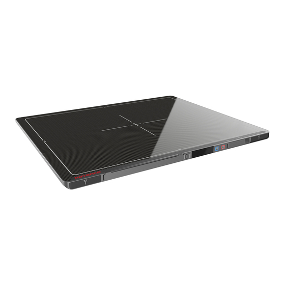
Product Introduction and Specification Product Features The Edge Air 1417 / 1417WCC are a wireless digital flat panel detector that has been designed for a faster, more streamlined approach to digital radiography systems. The Edge Air 1417 / 1417WCC detectors utilize a combination of propriety TFT glass and high quality scintillators, which along with a pixel pitch of 140 microns and assures delivery of sharp, high quality images. -
Page 24: Product Components
(110V or 220V 1.8m) (7m) LAN cable 1EA USB Cable 1EA for Trigger Cable 1EA (CAT 6, 10m) AGI Box 1EA AGI Box (straight-through) Dual Battery Charger Dual Battery Charger adapter 1EA 24 / 126 Edge Air 1417 / 1417WCC... -
Page 25: Part Names And Functions
Low battery (Battery remain 0~7%) Orange Low battery (Battery remain 7~15%) Link cable connector Use for data transfer and charging battery while wired mode is in use (Connect between detector and power supply.) Edge Air 1417 / 1417WCC 25 / 126... - Page 26 Battery : Rechargeable Lithium Ion battery(Charging Time-3 hrs) • In the diagram above, the box shows where the remaining battery percentage is displayed. Battery Remain Indicator Battery Level 75~100 % 50~75 % 25~50 % 0~25 % 26 / 126 Edge Air 1417 / 1417WCC...
- Page 27 25~50 % 0~25 % • Battery warranty period: 6 months Battery Charger : Two port cradle type LED Indicator Display battery charging status. LED Color Battery Status Green Fully charged Orange Charging Error Edge Air 1417 / 1417WCC 27 / 126...
- Page 28 P-interface cable or trigger cable. USB Connector This is a connector for communication between the AGI and PC. Connect the AGI to the PC by using a USB cable. 28 / 126 Edge Air 1417 / 1417WCC...
-
Page 29: Part Specifications
Network conditions and environmental factors, including volume of network traffic, building materials and construction, and network overhead, lower actual data throughput rate. Recommended Maximum operable distance : 10m (From the Access Point) Wireless Module and Wireless Antenna Edge Air 1417 / 1417WCC 29 / 126... - Page 30 Wireless module: The Rayence RWM001A 802.11 a/b/g/n/ac half mini PCI-e module is implemented. It supports 3T3R (3 transmit 3 receive) MIMO technology, which delivers throughput up to 1300Mbps. Edge Air 1417 / 1417WCC in the RF module does not use DFS band.
- Page 31 Weight 2.4.9 Cable (Optional) Parameter Length Unit Qty. Link cable (Optional) LAN cable (Optional) (CAT 6(straight-through), Optional) Power cord (110V or 220V) USB cable (Optional) Trigger cable (Optional) Micro USB cable (Optional) Edge Air 1417 / 1417WCC 31 / 126...
-
Page 32: Environmental Requirements
Environment Min. Max. Unit Note ℃ Temperature(Storage) ℃ Temperature(Operation) Humidity(Storage) % H.R. Humidity(Operation) % H.R. Pressure(Operation) 2.5.3 Grid Recommended Item Description 100~180 cm (40~72 inch) Ratio 8:1/10:1/12:1 Frequency 103, 215, 230 Line/inch 32 / 126 Edge Air 1417 / 1417WCC... -
Page 33: Dimensions (Unit: Mm)
PART I. User & Installation Manual Dimensions (Unit: mm) 2.6.1 Detector Edge Air 1417 / 1417WCC 33 / 126... - Page 34 PART I.User & Installation Manual 2.6.2 Battery 2.6.3 Mobile charger 2.6.4 Mobile charger adapter 34 / 126 Edge Air 1417 / 1417WCC...
- Page 35 PART I. User & Installation Manual 2.6.5 Power Supply (Optional) 2.6.6 Dual Battery Charger (Optional) Edge Air 1417 / 1417WCC 35 / 126...
- Page 36 PART I.User & Installation Manual 2.6.7 Dual Battery Charger Adapter (Optional) 2.6.8 AGI Box (Optional) 36 / 126 Edge Air 1417 / 1417WCC...
-
Page 37: Installation And Calibration
Installation and Calibration Installation 3.1.1 Software Installation Insert the CD that comes with the Detector. Install "setup.exe" from "\Release Davinci_version" and click "Next". Choose the model from the Detector Type list and click "Next". Edge Air 1417 / 1417WCC 37 / 126... - Page 38 Select “MultiByte-Character Set” and click “Next”. Choose UNICODE if console SW is supporting UNICODE. If Multibyte - Character set or UNICODE is not installed correctly, images will not be properly acquired. 38 / 126 Edge Air 1417 / 1417WCC...
- Page 39 PART I. User & Installation Manual Click “Install”. Click “Finish”. Edge Air 1417 / 1417WCC 39 / 126...
- Page 40 <Station Mode> Communicates with the wireless AP, and the wireless AP communicates with the PC through the LAN cable. (Wireless AP can select RAP001A provided by OSKO Inc. as option.) <AP Mode> Detector communicates with the PC without the wireless AP.
- Page 41 Auto Trigger & AP Mode Follow instructions from 3.1.4Product Set Up 2. Auto Trigger & AP Mode. Manual Trigger & Station mode Follow instructions from 3.1.4 Product Set Up 3. Manual Trigger & Station Mode. Edge Air 1417 / 1417WCC 41 / 126...
- Page 42 Manual Trigger & AP mode Follow instructions from 3.1.4 Product Set Up 4. Manual Trigger & AP Mode. Auto Trigger & Wired Mode Follow instructions from 3.1.4 Product Set Up 5. Auto Trigger & Wired Mode. 42 / 126 Edge Air 1417 / 1417WCC...
- Page 43 PART I. User & Installation Manual Manual Trigger & Wired Mode Follow instructions from 3.1.4 Product Set Up 6. Manual Trigger & Wired Mode. Edge Air 1417 / 1417WCC 43 / 126...
- Page 44 PART I.User & Installation Manual 3.1.4 Product Set Up 1. Auto Trigger & Station Mode Product Set up Connect the cable 1. Connect the wireless AP and PC with the LAN cable. 44 / 126 Edge Air 1417 / 1417WCC...
- Page 45 Desktop > Network Icon > Right click > Properties > Change Adaptor Settings • Control Panel > Network and Sharing Center > Change Adaptor Settings To use station mode, right click "Local Area Connection" and click Properties. Double click “Internet Protocol Version 4 (TCP/IPv4)”. Edge Air 1417 / 1417WCC 45 / 126...
- Page 46 Channel (Frequency) Avoid the crowded channel option. Recommend to use “Auto-Channel selection” function if external AP has the feature. Part.2 Service Manual Supplement 1. Refer to Wireless AP Set Up Instruction 46 / 126 Edge Air 1417 / 1417WCC...
- Page 47 2.2.2.101. If the IP address needs to be changed, please refer to 2.1 Detector IP Address Set Up in Part.2 Service Manual. If the detector does not communicate with the PC, please check the connection of the cable, PC set up and power of the detector. Edge Air 1417 / 1417WCC 47 / 126...
- Page 48 In Auto trigger mode, be sure to set the "Window time" longer than an exposure time. If the "Window time" is shorter than the exposure time, images will not be properly acquired. 48 / 126 Edge Air 1417 / 1417WCC...
- Page 49 Set up the Network as below. • Desktop > Network Icon > Right click > Properties > Change Adaptor Settings • Control Panel > Network and Sharing Center > Change Adaptor Settings Edge Air 1417 / 1417WCC 49 / 126...
- Page 50 "255.255.255.0" at the "Subnet mask". It is recommended to use the IP of the product independently of each other as it can cause PC disconnect when two or more products use the same IP. 50 / 126 Edge Air 1417 / 1417WCC...
- Page 51 LED Color Mode Orange Station Mode(Wireless) Green AP Mode(Wireless) MODE None Wired Mode Blinking Orange and Green Sleep Mode alternatively Choose the SSID (detector's SN) from Wireless Network Connection list. (PW: project302) Edge Air 1417 / 1417WCC 51 / 126...
- Page 52 In the AP mode, select "AP" from "Wireless Link Quality" and type the detector's serial number at the "SSID". If the detector does not communicate with the PC, please check the connection of the cable, PC set up and power of the detector. 52 / 126 Edge Air 1417 / 1417WCC...
- Page 53 In Auto trigger mode, be sure to set the "Window time" longer than an exposure time. If the "Window time" is shorter than the exposure time, images will not be properly acquired. Edge Air 1417 / 1417WCC 53 / 126...
- Page 54 Product Set up (with AGI) Connect the cable (with AGI box and AP) 1. Connect the wireless AP and PC with the LAN cable. 2. Connect the AGI box and PC with the USB cable. 54 / 126 Edge Air 1417 / 1417WCC...
- Page 55 PART I. User & Installation Manual 3. Connect the AGI box and generator with the P-interface or trigger cable. Instruction of P-interface cable Integration <Assembly Diagram> <Timing Chart> Instruction of Trigger Cable Integration <Assembly Diagram> <Timing Chart> Edge Air 1417 / 1417WCC 55 / 126...
- Page 56 Desktop > Network Icon > Right click > Properties > Change Adaptor Settings • Control Panel > Network and Sharing Center > Change Adaptor Settings To use station mode, right click "Local Area Connection" and click Properties. 56 / 126 Edge Air 1417 / 1417WCC...
- Page 57 Channel (Frequency) Avoid the Crowded channel option. Recommend to use "Auto-Channel selection" function if external AP has the feature. Part.2 Service Manual Supplement 1. Refer to Wireless AP Set Up Instruction Edge Air 1417 / 1417WCC 57 / 126...
- Page 58 IP Address Set Up in Part.2 Service Manual. If the detector does not communicate with the PC, please check the connection of the cable, PC set up and power of the detector. 58 / 126 Edge Air 1417 / 1417WCC...
- Page 59 Another window will be opened as below once the “Edit” button is pressed. Select "Manual" from "Trigger Mode". If "Window time" needs to be changed, type the value at "Window Time" from "Setting". Edge Air 1417 / 1417WCC 59 / 126...
- Page 60 PART I.User & Installation Manual 4. Manual Trigger & AP Mode Product Set Up (with AGI) Connect the cable (with AGI) 1. Connect the AGI box and PC with the USB cable. 60 / 126 Edge Air 1417 / 1417WCC...
- Page 61 PART I. User & Installation Manual 2. Connect the AGI box and generator with the P-interface or trigger cable. Instruction of P-interface cable Integration <Assembly Diagram> <Timing Chart> Instruction of Trigger cable Integration <Assembly Diagram> <Timing Chart> Edge Air 1417 / 1417WCC 61 / 126...
- Page 62 Desktop > Network Icon > Right click > Properties > Change Adaptor Settings • Control Panel > Network and Sharing Center > Change Adaptor Settings To use AP mode, right click "Wireless Network Connection" and click Properties. 62 / 126 Edge Air 1417 / 1417WCC...
- Page 63 LED Color Mode Orange Station Mode(Wireless) Green AP Mode(Wireless) MODE None Wired Mode Blinking Orange and Green Sleep Mode alternatively Choose the SSID (detector's SN) from Wireless Network Connection list. (PW: project302) Edge Air 1417 / 1417WCC 63 / 126...
- Page 64 In the AP mode, select "AP" from "Wireless Link Quality" and type the detector's serial number at the "SSID". If the detector does not communicate with PC, please check the connection of the cable, PC setup and power of detector. 64 / 126 Edge Air 1417 / 1417WCC...
- Page 65 Another window will be opened as below once the “Edit” button is pressed. Select "Manual" from "Trigger Mode". If the "Window time" needs to be changed, type the value at "Window Time" from "Setting". Edge Air 1417 / 1417WCC 65 / 126...
- Page 66 5. Auto Trigger & Wired Mode Product Set Up Connect the cable 1. Connect the power supply and PC with the LAN cable. 2. Connect the power supply and Detector with the Link cable. 66 / 126 Edge Air 1417 / 1417WCC...
- Page 67 Desktop > Network Icon > Right click > Properties > Change Adaptor Settings • Control Panel > Network and Sharing Center > Change Adaptor Settings To use Wired mode, right click "Local Area Connection" and click Properties. Double click “Internet Protocol Version 4 (TCP/IPv4)”. Edge Air 1417 / 1417WCC 67 / 126...
- Page 68 Connect the Detector to the power supply using the Link cable (Wired mode will be selected automatically) LED Color Mode Orange Station Mode(Wireless) Green AP Mode(Wireless) MODE None Wired Mode Blinking Orange and Green Sleep Mode alternatively 68 / 126 Edge Air 1417 / 1417WCC...
- Page 69 2.2.2.101. If the IP address needs to be changed, please refer to 2.1 Detector IP Address Set Up in Part.2 Service Manual. If the detector does not communicate with the PC, please check the connection of the cable, PC set up and power of the detector. Edge Air 1417 / 1417WCC 69 / 126...
- Page 70 In Auto trigger mode, be sure to set the "Window time" longer than an exposure time. If the "Window time" is shorter than the exposure time, images will not be properly acquired. 70 / 126 Edge Air 1417 / 1417WCC...
- Page 71 Product Set up (with Power supply and AGI) Connect the cable (with Power supply and AGI) Connect the power supply and PC with the LAN cable. Connect the power supply and Detector with the Link cable. Edge Air 1417 / 1417WCC 71 / 126...
- Page 72 Connect the AGI box and PC with the USB cable. Connect the AGI box and generator with the P-interface or trigger cable. Instruction of P-interface cable Integration <Assembly Diagram> <Timing Chart> Instruction of Trigger cable Integration <Assembly Diagram> <Timing Chart> 72 / 126 Edge Air 1417 / 1417WCC...
- Page 73 Desktop > Network Icon > Right click > Properties > Change Adaptor Settings • Control Panel > Network and Sharing Center > Change Adaptor Settings Set up SW To use Wired mode, right click "Local Area Connection" and click Properties. Edge Air 1417 / 1417WCC 73 / 126...
- Page 74 Connect the Detector to the power supply or RAP001A using the Link cable (Wired mode will be selected automatically) LED Color Mode Orange Station Mode(Wireless) Green AP Mode(Wireless) MODE None Wired Mode Blinking Orange and Green Sleep Mode alternatively 74 / 126 Edge Air 1417 / 1417WCC...
- Page 75 2.2.2.101. If the IP address needs to be changed, please refer to 2.1 Detector IP Address Set Up in Part.2 Service Manual. If the detector does not communicate with the PC, please check the connection of the cable, PC set up and power of the detector. Edge Air 1417 / 1417WCC 75 / 126...
- Page 76 Another window will be opened as below once the “Edit” button is pressed. Select "Manual" from "Trigger Mode". If "Window time" needs to be changed, type the value at "Window Time" from "Setting". (For change parameter settings, must click “Get Settings” button) 76 / 126 Edge Air 1417 / 1417WCC...
-
Page 77: Calibration
In order to properly acquire images, calibration must be performed. Without calibration, optimum images cannot be acquired. OSKO Inc. recommends to warm up the detector for 5 minutes after turning on the power. Calibration should be performed at regular intervals, typically once every six (6) months, or whenever the central beam of the X-ray source has been moved relative to the Detector. - Page 78 PART I.User & Installation Manual After checking connection, click “Calibration & Acquisition” tab. Click “Calibration”. 78 / 126 Edge Air 1417 / 1417WCC...
- Page 79 Dark frame is stored in “C:\davinci\cal”. A Calibration Point file will be created automatically. After acquiring the Dark frame, shoot an X-ray when the “Acquiring bright frame” window popup. Depending on the dark level of the product, 1~2 additional calibration points may be created. Edge Air 1417 / 1417WCC 79 / 126...
- Page 80 For each Calibration point, four images must successfully be acquired. After successfully doing so for every point, the Calibration process is complete. Click "OK" to move to the next step. 80 / 126 Edge Air 1417 / 1417WCC...
- Page 81 PART I. User & Installation Manual 3.2.2 Manual Bad Pixel Map Set Up Click “Calibration”. Click "View Frames". Edge Air 1417 / 1417WCC 81 / 126...
- Page 82 After completing step 5, check if bad pixel has been changed to green as Figure 2 - ❻. Click “Fill” at Figure 3 - ❼. Click "Save" at Figure 3 - ❽. Once setting BPMM is done, “BPMM.raw” file will be saved at C:\Davinci\CAL. 82 / 126 Edge Air 1417 / 1417WCC...
-
Page 83: Usage
Once the detector is connected, detector information is displayed in Detector Status and Link &Ready are checked as below. If "Detector Status" does not show anything, please refer to 3.1 Installation in Part.1 User & Installation Manual to connect the detector properly. Edge Air 1417 / 1417WCC 83 / 126... - Page 84 In order to change the size of an image, use "Crop Rows and Columns" as below. Click "Apply" to save. 4.1.3 Multi Detector Set Up Refer to 3 Multi Detector Set Up in Part.2 Service Manual for Multi-Detector Setting. 84 / 126 Edge Air 1417 / 1417WCC...
-
Page 85: Image Acquisition
Part.1 User & Installation Manual to connect the detector properly. If Calibration is not checked along with black dots checking off "Link" and "Ready" as above, please refer to 3.2Calibration in Part.1 User & Installation Manual and perform calibration again. Edge Air 1417 / 1417WCC 85 / 126... - Page 86 An acquired image will be stored in “C:\davinci\I.2440x2992” and the name of the file will be "(typed name from Step 1).raw”. The format of the stored file is 16 bit little-endian order. 86 / 126 Edge Air 1417 / 1417WCC...
-
Page 87: View Images
PART I. User & Installation Manual View Images 1. Click “View Images” 2. Another window will be popped up as below. Histogram Set Up Edge Air 1417 / 1417WCC 87 / 126... - Page 88 PART I.User & Installation Manual Pixel value at certain level Choose "S" from marked box. Profile for horizontal line Choose "R" from marked box. 88 / 126 Edge Air 1417 / 1417WCC...
-
Page 89: Additional Function
Profile for vertical line Choose "C" from the marked box. Additional Function 4.4.1 Battery Remain Once you click "Get Image" under the "Calibration & Acquisition” tab, the Status window will show how much battery remains. Edge Air 1417 / 1417WCC 89 / 126... - Page 90 Once you click "Get Image" under the "Calibration & Acquisition” tab, the Status window will show the strength of the wireless signal. Before you check the wireless signal in the AP mode, the detector's serial number should be entered at the "SSID". 90 / 126 Edge Air 1417 / 1417WCC...
- Page 91 To turn off Sleep Mode, attempt to acquire an image or press the power button on the detector just once. A normal image can be acquired after 10 seconds Sleep Mode has been turned off. Edge Air 1417 / 1417WCC 91 / 126...
- Page 92 (For change parameter settings, must click “Get Settings” button) By unchecking 4x4 Binning, a normal image preview appears. By unchecking Preview, a full frame image appears. 92 / 126 Edge Air 1417 / 1417WCC...
- Page 93 The last acquired image can be opened by clicking "Recent Frame" under the "Calibration & Acquisition” tab. 4.4.6 Restore Connection When the connection between the detector and PC is lost, the connection can be made again by clicking "Restore Connection" under the "Calibration & Acquisition” tab. Edge Air 1417 / 1417WCC 93 / 126...
- Page 94 For Storage Viewer, must running DBMS and Web Server environment For running Storage Viewer environment, OLED is displayed “Check DB Server” Stored Image can be opened and deleted by referring SDK 94 / 126 Edge Air 1417 / 1417WCC...
-
Page 95: Maintenance
C. Ater enter to worklist menus, click ‘+’ icon and create worklist info. D. Can see all worklist for will acquire image. Click ‘Capture’ button. In detector ready status, can take X-ray image. Edge Air 1417 / 1417WCC 95 / 126... - Page 96 G. Show all acquisition image list on Storage Mode When worklist menu is empty, detector will be created woklist menu and matching Some guide image is created by web server demo mode 96 / 126 Edge Air 1417 / 1417WCC...
- Page 97 - Will Show the PSK information of detector IP Menu - Will Show the IP information of detector Mask menu - Will Show the Mask information of detector Factory reset menu - Factory reset menu Edge Air 1417 / 1417WCC 97 / 126...
- Page 98 Click “Calibration & Acquisition” tab ❸ Click “Edit” button ❹ Check “GPR Enable” check box when using an analog grid ❺ Click “Grid Type” combobox ❻ Select a GPR parameter Click “OK” button 98 / 126 Edge Air 1417 / 1417WCC...
- Page 99 GPR Parameter Select a parameter in consideration of the used grid specification & detector model. 1417 model(Edge Air 1417 / 1417WCC) use to Automatic parameter recommended 1717 model(Edge Air) use to Vertical Parameter recommended. Edge Air 1417 / 1417WCC...
-
Page 100: Maintenance
Inspection In order to ensure that the detector is used safely and normally, please be sure to inspect the product regularly before use. If any problem occurs, please contact OSKO Inc. Customer Serviceteam. Please perform inspections based on the check list below. -
Page 101: Replaceable Parts And Instruction Of Replacement
Press the fuse as below and pull the fuse box. Pull the fuse and replace with another fuse. 5.3.2 Power cord: H05VV-F 0.75SQ * 3C 5.3.3 Ethernet Cable: UTP 4PR 24AWG (CAT.7) Edge Air 1417 / 1417WCC 101 / 126... -
Page 102: Disposal Or Recycling
For more detailed information about recycling this product, please refer to local governing ordinances and recycling plans. 102 / 126 Edge Air 1417 / 1417WCC... -
Page 103: Warranty
OSKO Inc., at its option, shall repair, rebuild or adjust the affected parts. OSKO Inc. shall have no obligation for any defects to the extent that such defect arises out of (i)normal and fair wear and tear or Product which has been modified without OSKO Inc.'s approval, (ii) Product which has not been installed in strict conformity to the OSKO Inc.'s... -
Page 105: Service Manual
PART II. Service Manual 1. Overview ............106 (IP, SSID Set Up / 2. FPD Manager Instruction Firmware, FPGA Update) ......107 3. Multi Detector Set Up........115 4. Troubleshooting ........... 119 Edge Air 1417 / 1417WCC 105 / 126... -
Page 106: Overview
PART II.Service Manual Overview This service manual gives additional instructions for setting up the detector. Edge Air 1417 / 1417WCC 106 / 126... -
Page 107: Fpd Manager Instruction (Ip, Ssid Set Up / Firmware, Fpga Update)
After the power of detector is on, open "FPD_Manager.exe". Type detector's current IP address at "Detector IP Address" from "Current Setting" as below. Detector's Ethernet Controller is operated with Second IP address, 192.168.124.80. Edge Air 1417 / 1417WCC 107 / 126... - Page 108 Click "OK" once the message below pops up. Click "OK" again once the message below pops up. Turn off the power of the detector and after 5 seconds, turn the power back on. Edge Air 1417 / 1417WCC 108 / 126...
-
Page 109: Ssid, Psk (Pre-Shared Key) Set Up
Type the detector's current IP address in "Detector IP Address" from "Current Setting" as below. Detector's Ethernet Controller is operated with Second IP address, 192.168.124.80. Current SSID and PSK (Pre-Shared Key) is displayed once the "Get Current Settings" button is pressed. Edge Air 1417 / 1417WCC 109 / 126... - Page 110 AP Mode connection quality. If the Channel causes conflict, the channel can be changed through this program. Click "OK" once the message below pops up. Turn off the power of detector and after 5 seconds, turn the power back on. Edge Air 1417 / 1417WCC 110 / 126...
-
Page 111: Firmware, Fpga Update
After the power of detector is on, open "FPD_Manager.exe". Type the detector's current IP address in "Detector IP Address" from "Current Setting" as below. Detector's Ethernet Controller is operated with Second IP address, 192.168.124.80. Edge Air 1417 / 1417WCC 111 / 126... - Page 112 Click "OK" once the message below pops up. Turn off the power of detector and after 5 seconds, turn the power back on. Detector IP address might be changed to 192.168.1.80 after updating depends on Firmware. Edge Air 1417 / 1417WCC 112 / 126...
-
Page 113: Set Windows Firewall To Use Fpd_Manager (For Win 7)
‘Control Panel’ -> ‘Windows Firewall’ -> ‘Allow an app or feature through Windows Firewall’ Check "Name", "Private" and "Public" if FPD_Manager program is already on the list. Click "Allow another app..." when FPD_Manager program is not on the list. Edge Air 1417 / 1417WCC 113 / 126... - Page 114 PART II.Service Manual Select the program and add if it is already on the list. Click "Browse" when the program is noon the list. Browse and open FPD_Manager program and repeat step ②. Edge Air 1417 / 1417WCC 114 / 126...
-
Page 115: Multi Detector Set Up
PART II. Service Manual Multi Detector Set Up Open “_vadav.lnk” from "C:\davinci”. Click "Edit" under the "Settings" tab. Select "Detector #1". Choose the product model and type the IP address. Edge Air 1417 / 1417WCC 115 / 126... - Page 116 Click "Edit" from "Detector #1". Set up the "Trigger Mode" and "Setting". (For change parameter settings, must click “Get Settings” button) Select "Detector #2". Choose the product model and type the IP address. Edge Air 1417 / 1417WCC 116 / 126...
- Page 117 Click "Edit" from "Detector #2". Set up the "Trigger Mode" and "Setting". (For change parameter settings, must click “Get Settings” button) If a third detector is being used, select "Detector #3". Choose the product model and type the IP address. Edge Air 1417 / 1417WCC 117 / 126...
- Page 118 The calibration folder is named according to the third and fourth numbers of the IP address. (e.g. C:\Davinci\CAL_ 01_80) For further instructions on calibration, please refer to 3.2Calibration in Part.1 User & Installation Manual. Edge Air 1417 / 1417WCC 118 / 126...
-
Page 119: Troubleshooting
If any problem occurs during the usage of the product, please use this chapter as a troubleshooting guide. Follow the instructions to resolve the problem. If the problem is not resolved, please contact our OSKO Inc. Customer Service team (E-mail: service@oskomedical.com). LAN Connection Issue 1. Wireless Mode 1. - Page 120 Check the link cable and the power cord are connected properly Check that the power of the detector is on. 2. Check PC Set up Make sure that the IP address is set to “2.2.2.20”from" Internet Protocol Version4 (TCP/IPv4)" Edge Air 1417 / 1417WCC 120 / 126...
-
Page 121: Lost Ip Address (Use One Of The Methods Below)
Press the “Reset” button to reset the IP address. (Default IP : 2.2.2.100) When using a reciprocating bucky If there is image noise casued by the electromagnetic, follow the instructions below. Open “_vadav.lnk” from "C:\davinci”. Click the "Calibration & Acquisition" tab. Click "Edit". Edge Air 1417 / 1417WCC 121 / 126... - Page 122 PART II.Service Manual Change "window time" from 2 to 4 sec and click “OK” (For change parameter settings, must click “Get Settings” button) The Window time default value is 0.5sec Edge Air 1417 / 1417WCC 122 / 126...
-
Page 123: Auto Trigger Mode
Click the "Calibration & Acquisition" tab. Click "Edit". Change "Auto Trigger Threshold" from 5 to 100 and click "OK". (For change parameter settings, must click “Get Settings” button) The Auto Trigger Threshold default value is 15 Edge Air 1417 / 1417WCC 123 / 126... -
Page 124: Supplement.1 Generator Specification
Range mAs Range kV Range 40 ~ 150 kV 1.0 ~ 1000 mA 0.1 ~ 1000 mAs If you need further information for generators, please contact your OSKO Inc. representative. Edge Air 1417 / 1417WCC 124 / 126... - Page 126 OSKO Inc. 8085 NW 90th Street, Miami, Florida, 33166 U.S.A. Tel: +1-305-599-7161 E-Mail: service@oskomedical.com www.OSKOMEDICAL.com...
Need help?
Do you have a question about the Edge Air 1417 and is the answer not in the manual?
Questions and answers