Advertisement
Quick Links
Operation's manual Rheometer MDR-01
1. Specifications
- Reference Standard
- Pressure system
- Die configuration
- Temperature System
- Temperature range
- Oscillation frequency
- Oscillation angle
- Drive Motor
- Torque Measurement
- Torque Calibration
- Operation Panel
- Measured Time
- Communication Data
- Associated program (Option)
- Power Supply
- Air Pressure
- Dimension
- Weight
ISO 6502, ASTM D5289
Air cylinder system
Biconical Die, close die system, sealed
PID Microprocessor Controlled
Probe RTD Pt 100 Ω(Class A)
Room Temp. (+25 °C) to 250 °C
Resolution 0.1
°C Units °C/ °F
100 cpm. (1.667 Hz)
0.5°±0.03°, 1°±0.03°
Servo Motor
Torque Transducer (Direct Torque Measurement)
Standard Torque Reference value
Capacitive Touch Screen, 5 Inches (Standalone)
1/60 sec, 1/100 sec
Unit (min-min/ min-sec/ sec)
RS-232
Data Process Software
220 VAC ±10 VAC, 50/60 Hz, 6 A
4.0 bar to 5.0 bar
Width 50.0 cm., Depth 54.5 cm., Height 105 cm.
140 kg.
1
Advertisement

Summary of Contents for CGM MDR-01
- Page 1 Operation’s manual Rheometer MDR-01 1. Specifications - Reference Standard ISO 6502, ASTM D5289 - Pressure system Air cylinder system - Die configuration Biconical Die, close die system, sealed PID Microprocessor Controlled - Temperature System Probe RTD Pt 100 Ω(Class A) Room Temp.
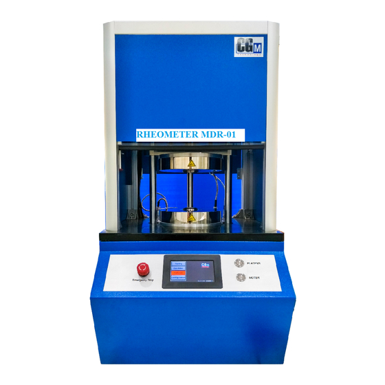
- Page 2 Operation’s manual Rheometer MDR-01 2. Components Figure 1 Front image of the MDR-01 Figure 1, illustrates the components of the front perspective of the MDR -01, as follows; No. 1: The Upper Plate, which consists of the Upper die, Heater, and Probe Sensor No.
- Page 3 Operation’s manual Rheometer MDR-01 Figure 2 Internal Components of the MDR-01 Figure 2, illustrates the internal components of the MDR -01, as follows; No. 7: Servo Motor No. 9: Transformer No. 8: Thermostat No. 10: Adjustable leg stand No. 11: Main control panel...
- Page 4 Operation’s manual Rheometer MDR-01 Figure 3 Side image of the MDR-01 Figure 3, illustrates the side perspective of the MDR -01, as follows; No. 12: RS323 outlet for connection to a computer or printer No. 13: Power outlet (220 VAC)
- Page 5 Operation’s manual Rheometer MDR-01 Figure 4 Rear image of the MDR-01 Figure 4, illustrates the rear components of the MDR -01, as follows; No. 15: Air Muffler No. 16: Air ventilator No. 17: Air intake, which is connected to the Air Regulator...
-
Page 6: Installation
1. Set the device to a level position For users 3.2) 1. Site preparation for the installation of MDR-01 - Grounded power outlet with a 220 VAC 50Hz/60Hz capacity, that can discharge at no less than 6 Amp - Compressed air supply of at least 4-5 bars - Support structure to place the MV-01, which can withstand a weight of 200 kg. - Page 7 4. How to use the touch screen panel of the Rheometer MDR-01 After powering up the MDR-01, the main screen display will be as indicated in Figure 5, which is used for monitoring and tracking of the test results. The main functions will consist of Testing, Condition, Calibrate, and Configuration.
- Page 8 Operation’s manual Rheometer MDR-01 Figure 6 shows the main display of the Testing mode Figure 7 shows the resulting display when A is selected Note: Pressing A area on touch screen for switching the display between Figure 6 and Figure 7.
- Page 9 Operation’s manual Rheometer MDR-01 4.1.1) STANBY is the ready function, waiting for the samples to be tested. See example below. Figure 8 shows the display screen in the STANBY mode 4.1.2) RESULT, will show the test results, as can be seen in Figure 9.
- Page 10 Operation’s manual Rheometer MDR-01 Scorch time 1, time from the start where torque equal ML to the time where torque equal ML+1 Scorch time 2, time from the start where torque equal ML to the time where torque equal ML+2...
- Page 11 Operation’s manual Rheometer MDR-01 4.2) Condition When “Condition” is selected, you will enter into the Condition page, which will display the conditions of the sample test. The parameters can be adjusted to suit the test sample, as shown in Figure 11...
- Page 12 Operation’s manual Rheometer MDR-01 4.2.2) Functions 1. Time Set : is the function that determines the time required to test the sample (with a range of 0–99 minutes) . For example; to set the time for 1 minute, just press “1” and then “E” to confirm.
- Page 13 Operation’s manual Rheometer MDR-01 7. I-Time : is starting time function before finding ML values. Starts from plate is closed. (ranges 0-99 seconds) For example; to set the time 13 seconds, just press “13”and then “E” to confirm. The machine will be started after plate was closed 13 seconds.
- Page 14 Operation’s manual Rheometer MDR-01 Figure 13 shows the main display of the Configuration Torque Select A area to set Torque Standard unit for Calibrate (dNm, lbin, and kg-f). Select B area to set STD Torque value according to Correction Torque Standard value for Calibrate.
- Page 15 Operation’s manual Rheometer MDR-01 4.3.3) is torque calibration sensor function of MDR- 01 with Standard torque. To enable the operators to correctly calibrate the device. 4.3.4) Checking the operating status of the device. Function Status Response When “Motor” is selected, the color of the button will change to red, and the motor will start to rotate.
- Page 16 Operation’s manual Rheometer MDR-01 4.4.1) Temp. Parameter Temp. Parameter, will display the functions for monitoring the operating temperature range, as shown in Figure 15. Figure 15 shows the Temp. Parameter screen 4.4.2) Temp. Auto tune Temp. Auto tune, is used to adjust the temperature controls, as shown in...
- Page 17 Operation’s manual Rheometer MDR-01 4.4.3) Temp. Offset Temp. Offset, is used to the parameters of the temperature, as shown in Figure 17. Note: The use of this function must be used under the calibration by an experienced engineer. Figure 17 shows the Temp. Offset screen 4.4.4) I/O Check...
- Page 18 Operation’s manual Rheometer MDR-01 4.4.5) Machine Check Machine Check, is used to verify the status of the test device, as shown in Figure 19. Note: The use of this function must be used under the calibration by an experienced engineer.
- Page 19 Operation’s manual Rheometer MDR-01 4.4.7) Communication Check Communication Check, is used to check on the communication status of the connected internal and external test device, as shown in Figure 21 Note: The use of this function must be used under the calibration by an experienced engineer.
- Page 20 Operation’s manual Rheometer MDR-01 5. How to use the Computer System Operations Double-click on the “RHEO” icon to activate the system, which will display the main operating screen, as shown in Figure 22. 5.1) Main Menu descriptions Figure 22 Main Menu of the system From Figure 22, the main components of the Main Menu can be explained, as follows;...
- Page 21 Operation’s manual Rheometer MDR-01 No. 7 Space to input the test sample name No. 8 Latest test results No. 9 Graph displaying the Torque and temperature test results No. 10 Test results table, the latest result is displayed on 1st row.
- Page 22 Operation’s manual Rheometer MDR-01 Figure 24 shows the Spec results screen [ Delete (F4) ] is used to delete the data. Choose the data to be deleted, 5.2.2) and press F4. [ Setup (F5) ] By pressing the Setup (F5) or F5 on the keyboard, will 5.2.3)
- Page 23 Operation’s manual Rheometer MDR-01 1.1) Click on the blank space in the table. 1.2) Click on “Registor (F2)” or F2 on the keyboard. This will display the “Rheograph Input form” window, as shown in Figure 26, in order to create a new test sample name and the test conditions.
- Page 24 Operation’s manual Rheometer MDR-01 No. 10 Type of required test - ts is Scotch time. For example; ts1 is period of time where torque equal lowest torque value +1 (ML+1). Start counting from point of lowest torque value. - tc is Cure time.
- Page 25 Operation’s manual Rheometer MDR-01 Figure 27 shows ExcelForm screen From Figure 27, the various options of the ExcelForm can be explained, as follows; No. 1 Format of the required result. No. 2 Range of the required result. No. 3 Excel Data save button.
- Page 26 Operation’s manual Rheometer MDR-01 5.2.5) [Update (F8)] Can be used for renaming the test samples. It can be done by clicking on the test sample name which needs to be renamed (from the test results table), and edit in the Sample Name field (No. 7, from Figure 22). Finally, press “Update (F8)”...
- Page 27 Operation’s manual Rheometer MDR-01 Examples of the test result graphs Histogram X-R graph Test results and accompanying graph...
- Page 28 Operation’s manual Rheometer MDR-01 6. How to use Rheometer MDR-01 The MDR-01 device can be used by 2 modes of operations; by the touch screen in the Standalone mode, and by using in conjunction with the “RHEO” (computer mode). 6.1 How to use in the “Standalone” mode.
- Page 29 Operation’s manual Rheometer MDR-01 Figure 31 shows placing rubber for testing 6.1.5) Press the CLOSE button, in order to activate the testing process of the MDR-01. During the testing process, real-time monitoring can be observed by selecting “RESULT” or “GRAPH” on the touch screen.
- Page 30 Operation’s manual Rheometer MDR-01 6.2.6) Press the CLOSE button, in order to activate the testing process of the MDR-01. During the testing process, real-time monitoring can be observed by selecting “RESULT” or “GRAPH” on the touch screen. 6.2.7) When the test is completed, the plate and the front panel will open automatically.
- Page 31 7. Calibration 7.1. Calibrate : Sensor for reading Torque value, MDR-01 Calibrate Sensor for reading Torque value, MDR-01 can be preceded by Torque Standard. For this example, Torque Standard is used for explanation as Figure 32. Figure 32 Sample of Torque Standard Calibrate Sensor for reading Torque value, MDR-01.
- Page 32 Note: Torque unit and STD Torque depend on torque angle of Rheometer (Oscilla-tion angle) and temperature for Calibrate specified in Torque Standard from manufacturer. For example as Figure 35, Rheometer MDR-01 set angle at 0.5 degree. Figure 35 shows parameter values of Torque Standard 7.1.6) After set parameter values for Calibrate completely, press...
- Page 33 Operation’s manual Rheometer MDR-01 7.1.7) Press 7.1.8) Torque Standard input screen will be displayed as Figure 36. Figure 36 shows the screen after press Torque Calibrate button 7.1.9) Place Torque Standard at the center between Upper die and Lower die as Figure 37.
- Page 34 Operation’s manual Rheometer MDR-01 7.1.10) Press button for close the front panel and move the upper plate press the Torque Standard as Figure 38. Figure 38 shows the position of upper plate when press down 7.1.11) Then the machine will start to warm up Torque Standard. The screen as Figure 39 will be displayed.
- Page 35 7.1.14) Press for open the front panel and lift the plate up. Due to remaining high 7.1.15) Move the Torque Standard carefully as figure 41 temperature. Figure 41 shows how to move Torque Standard out of MDR-01...
- Page 36 Operation’s manual Rheometer MDR-01 7.1.16) Press for returns to main screen. 7.2 Calibrate Temperature of MDR-01 Calibrate Temperature of MDR-01 must be used by an experienced engineer.
- Page 37 Operation’s manual Rheometer MDR-01 Basic Maintenance of the MDR-01 MDR-01 using, required maintenance from user. In order to test effectively and provide test results accurately. The basic maintenance steps as follows; 8.1 Loosen 2 screws as shown in Figure 42 Figure 42 shows removal Cover from the Lower Die by remove 2 screws 8.2 Remove Cover from the Lower Die for cleaning, as Figure 43.
- Page 38 Operation’s manual Rheometer MDR-01 8.3 Use a brass wire brush to clean the lower die, as shown in Figure Figure 44 shows the cleaning of the lover die 8.4 Use a sharp steel rod to replace the old O-ring from Cover of the lower die, as shown in Figure 45.
- Page 39 Operation’s manual Rheometer MDR-01 8.5 Cleaning the O-ring groove in Cover Lower Die. 8.6 Replace the original O-ring with a new one, as shown in Figure 46. Figure 46 shows replacement the original O-ring with a new one 8.7 Use Jig for supporting O-ring replacement as Figure 47.
- Page 40 Operation’s manual Rheometer MDR-01 8.8 Place Cover into the Lower Die by pressing Cover until it set in position. Jig is pushed up as figure 48. Figure 48 shows the assembly Cover after replacement O-ring 8.9 After remove Jig, Tighten the screws to secure Cover, as Figure 49.
- Page 41 Operation’s manual Rheometer MDR-01 8.10 Replacement Cover from O-ring of Upper Die with the same method as the Lower Die (No. 8.1-8.9) as Figure 50. Figure 50 shows removal Cover from the Upper Die by remove screws. Notes: 1. Clean the upper and lower with a brass wire brush, at least once per day.
Need help?
Do you have a question about the MDR-01 and is the answer not in the manual?
Questions and answers