
Related Manuals for Stone Age WARTHOG WGR MAGNUM Series

Summary of Contents for Stone Age WARTHOG WGR MAGNUM Series
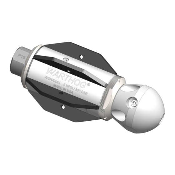
- Page 1 WGR MAGNUM SERIES CONTROLLED ROTATION SEWER NOZZLE AND SWITCHER HEAD USER MANUAL PL 533 REV G (04/2020)
-
Page 2: Table Of Contents
TABLE OF CONTENTS MANUFACTURER’S INFORMATION ............3 SPECIFICATIONS. -
Page 3: Manufacturer's Information
MANUFACTURER’S INFORMATION StoneAge Inc. StoneAge NL 466 S. Skylane Drive Reedijk 7Q Durango, CO 81303, USA 3274 KE Heinenoord Phone: 970-259-2869 Netherlands Toll Free: 866-795-1586 (+31) (0) 85 902 73 70 www.stoneagetools.com sales-NL@stoneagetools.com This manual must be used in accordance with all applicable national laws. The manual shall be regarded as a part of the machine and shall be kept for reference until the final dismantling of the machine, as defined by applicable national law(s). -
Page 4: Tool Overview
WGR MODELS AND HEAD SPECIFICATION INFORMATION TOOL CONFIGURATION Warthog sewer nozzles come in standard, descaling, and pulling configurations. Standard nozzles utilize controlled rotation technology and a balanced jetting configuration to deliver superior results in nearly all applications. We also offer nozzles that tune descaling or pulling performance for a variety of special conditions. -
Page 5: Tool Weights And Dimensions
TOOL WEIGHTS AND DIMENSIONS DESCRIPTION: The Magnum Series Warthog WGR (hereafter WGR) Controlled Rotation Sewer Nozzle is designed for waterjet cleaning of pipes and sewer lines. • Jet thrust from the water powers the rotation of the head and pulls the tool through the line. Front Jet •... -
Page 6: Warning And Safety Instructions
WARNING AND SAFETY INSTRUCTIONS OPERATOR TRAINING Operators MUST read, understand, and follow the Operational and Training Requirements (Section Managers, Supervisors, and Operators MUST be 7.0) of WJTA-IMCA’s Recommended Practices For trained in Health and Safety Awareness of High- The Use Of High-pressure Waterjetting Equipment, pressure Water Jetting and hold a copy the Water or equivalent. - Page 7 WARNING AND SAFETY INSTRUCTIONS PRE-RUN SAFETY CHECK WARNING Refer to WJTA-IMCA’s, Recommended Practices Operations with this equipment can be potentially For The Use Of High-pressure Waterjetting hazardous. Caution MUST be exercised prior Equipment and/or The Water Jetting Association’s, to and during equipment and water jet tool use. WJA Code of Practice for additional safety Please read and follow all of these instructions, information.
-
Page 8: Operation
OPERATION DANGER Do not attempt to clean a manhole with the WGR hanging by the hose. The tool can turn around and strike the Operator. Specific accessories are offered and are required to safely clean manholes. Do not allow the tool to enter a manhole or vault while in operation. If the tool is not contained in a pipe it presents a serious hazard and if not avoided could result in death or serious injury. -
Page 9: Troubleshooting
TROUBLESHOOTING HEAD WILL NOT ROTATE: • Check to see if any jets, or inserts, are plugged. Even if a jet is only partially blocked it can keep the head from rotating. Jets must be removed from the head to be properly cleaned. Poking the material plugging the jet back into the head will not fix the problem because it will re-plug the jet once water starts flowing. -
Page 10: Fluid Replacement
FLUID REPLACEMENT SPEED CONTROL FLUID CHANGE The speed control fluid changing is made easy with the WGR and disassembly of the tool is not required. This means there is less chance for contamination and longer overall tool life. Fluid changes should only be performed by qualified persons. -
Page 11: Wgr Magnum Maintenance Tools And Materials
MAINTENANCE TOOLS AND MATERIALS Product training and proper tools are required to service this nozzle. If you are uncomfortable performing the service, bring the nozzle to your authorized dealer. The use of a bench vise and an arbor press is recommended. Take care throughout the entire procedure to keep the internals clean and free from grit, lint, and contamination. -
Page 12: Disassembly
DISASSEMBLY 2. Keep the flats of the Front Nut clamped DISASSEMBLY down in a bench vise with the Inlet Nut 1. Remove the Head by clamping it in a vise facing up for the next step. with the Inlet Nut facing up. Push the 3. - Page 13 DISASSEMBLY 4. With the Body still in the vise, use an 7. Remove the Port Plug that is closest to the Automotive Sliding Wrench on the flats of Front Nut with a medium size, flat-head, the Body to carefully hold it in place. Use screw driver.
- Page 14 DISASSEMBLY 9. Carefully clamp the flats of the Body down 11. Using a pick, remove the Shaft Seal and in a bench vise. Using a Automotive Sliding O-Ring from the Front Nut. Wrench, remove the Front Nut from the Body. WGR 006 Shaft Seal WGR 008...
- Page 15 DISASSEMBLY 14. Squeeze the HP Seal Puller together and 16. Evenly seat a Bearing Splitter under the Rear insert it into the bore of the Shaft HP Seal, Bearing then press on the end of the Shaft then release. The HP Seal Puller should to remove Bearing.
-
Page 16: Assembly
ASSEMBLY 3. Install the Shaft Seal with the lip spring ASSEMBLY facing down into the Inlet Nut. Generously NOTICE coat the inside of the Shaft Seal with grease. Wash all appropriate parts in solvent and blow The O-Ring (WG 008) seats around the base dry before assembling. - Page 17 ASSEMBLY 11. Install the assembled Front Nut. Apply anti- TECH TIP: seize to the threads of the Body and torque Before proceeding; The use of an Arbor Press to 115-135 ft-lbs. and Install Tube (WGR 182) is recommended for the next three steps. WGR 004 Front Nut 8.
- Page 18 ASSEMBLY NOTICE TECH TIP: The rotation speed of the head can be fine tuned Before proceeding; The use of an Arbor Press with three different viscous fluid choices to and Install Tube (WGR 182) is recommended for optimize performance for specific applications; the next three steps.
- Page 19 ASSEMBLY 21. Install the O-Ring (WGR 050) into the bore 25. Generously coat the Wave Spring with for the Shaft HP Seal. Install the O-Ring grease. Drop into the Body on top of the (TR200 121) into the groove before the start Bearing.
- Page 20 ASSEMBLY 29. Install the Head by clamping the flats in a TECH TIP: vise with the threads facing up. Keep the flats of the Front Nut clamped down in a bench vise on with the Inlet Nut facing up for 30.
-
Page 21: Wgr Switcher 1 And 1¼
WGR SWITCHER OVERVIEW DESCRIPTION AND INTENDED USE: WGR SWITCHER PARTS The Switcher is designed to allow an operator to MODEL: “switch” between a pulling/flushing mode and CNP2 XXX Jets a cleaning mode while using the same head. GP 025-SS-P2 Plug This is made possible by an internal mechanism called a Poppet. -
Page 22: Operation And Troubleshooting
WGR SWITCHER OPERATION AND TROUBLESHOOTING OPERATION: Install the WGR Switcher Nozzle onto the hose end. Position hose and nozzle into the pipe to be cleaned. We recommend running the nozzle into the pipe about 3-5 feet. Verify switcher’s position of by bringing the nozzle up to operating pressure. -
Page 23: Wgr Switcher Disassembly
WGR SWITCHER DISASSEMBLY 4. Remove the Front Jet from the Front Port with DISASSEMBLY a 3/8” Nut Driver. 1. Secure the wrench flats of the Switcher Head in a vise with the Bushing facing up. Front Jet 2. Using an Automotive Sliding Wrench, break the Bushing loose from the Head and contin- ue to remove it by hand. -
Page 24: Wgr Switcher Assembly
WGR SWITCHER ASSEMBLY ASSEMBLY 4. Install the Spring into the center of the NOTICE Cartridge Assembly. 5. Press the Poppet into the Head assembly If reusing parts instead of replacing them; and rotate while pressing until its held in • Wash all parts thoroughly in solvent and blow dry place. -
Page 25: Wgr And Switcher Maintenance Schedule
WGR MAGNUM AND SWITCHER MAINTENANCE SCHEDULE ITEM FREQUENCY MAINTENANCE REQUIRED • Rinse the nozzle with clean water to remove debris between the Weekly Nozzle head, body and shaft. • Inspect all inserts for blockages. • Remove inserts with blockages and clean and dry them thoroughly. •... -
Page 26: Part Names/Numbers And Service Kits
PART NAMES/NUMBERS AND SERVICE KITS 319-F-T06 WGR 081 or 082 GS 519-02 WGR 076 WGR 050 WGR 006 WGR 059-M90 Washers (6) Fins (6) Screws (6) O-Ring O-Ring Shaft Seal Nut HP Seal WGR 082 Fins are available for 10”-12” pipe WGR 020 or *WGR 022 WGR 102-P16 or *WGR-102-P20 WGR 008... - Page 27 NOTES PAGE LEFT BLANK INTENTIONALLY 866-795-1586 • WWW.SEWERNOZZLES.COM...
-
Page 28: Terms And Conditions And Warranty
TERMS AND CONDITIONS AND WARRANTY INFORMATION 1. Acceptance of Terms and Conditions. Receipt of these 4. Delivery. Seller is not obligated to make delivery by a Terms and Conditions of Sale (“Terms and Conditions”) specified date, but will always use its best efforts to make shall operate as the acceptance by StoneAge, Inc. - Page 29 TERMS AND CONDITIONS AND WARRANTY INFORMATION 9. Governing Law. All sales, agreements for sale, offers to 11. Attorney’s Fees. If any litigation is commenced sell, proposals, acknowledgments and contracts of sale, between Seller and Buyer, or their personal representatives, including, but not limited to, purchase orders accepted by concerning any provision hereof, the party prevailing in the Seller, shall be considered a contract under the laws of the litigation shall be entitled, in addition to such other relief that...
- Page 30 TERMS AND CONDITIONS AND WARRANTY INFORMATION WARRANTY: Warranties set forth herein extend only to End-Users, to End-User, and StoneAge is not obligated to make the meaning customers acquiring, or that have previously same improvements during warranty service to any Product acquired, a product manufactured by StoneAge (“Product”) previously manufactured.
- Page 31 TERMS AND CONDITIONS AND WARRANTY INFORMATION 7. LIMITATION OF LIABILITY. End-User specifically Some jurisdictions do not allow the limitation or exclusion acknowledges that the Product may be operated at high of liability for certain damages, so the above limitations and speeds and/or pressures, and that as such it may be exclusions may not apply to you.
- Page 32 1-866-795-1586 • www.STONEAGETOOLS.com © 2020 StoneAge, Inc. All Rights Reserved...
Need help?
Do you have a question about the WARTHOG WGR MAGNUM Series and is the answer not in the manual?
Questions and answers