Advertisement
Quick Links
Soundshield Assembly Instructions
Corporate Headquarters
4420 14th Avenue NW
Seattle, WA 98107
Tel: (206) 789-3880
Fax: (206) 782-5455
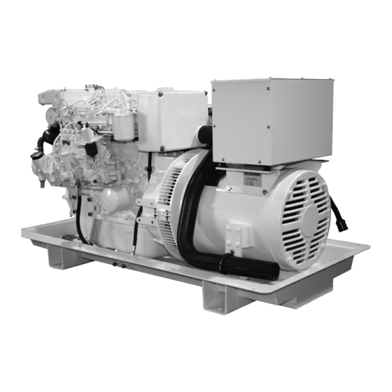
M944W
Alaska Branch Office
1200 West International
Airport Road
Anchorage, AK 99519
Tel: (907) 562-2222
Fax: (907) 563-1921
www.northern-lights.com
Southeastern U.S.A.
1419 W Newport Center Dr
Deerfield Beach, FL 33442
Tel: (954) 421-1717
Fax: (954) 421-1712
East Coast Branch
Gulf Branch
15 Aegean Dr.
19 Veterans Memorial Blvd.
Suite 4
Kenner, LA 70062
Methuen MA 01844
Tel: (504) 360-2180
Tel: (978) 475-7400
Toll Free: (800) 843-6140
Fax: (978) 475-7745
Advertisement

Subscribe to Our Youtube Channel
Related Manuals for Northern Lights M944W


Summary of Contents for Northern Lights M944W
- Page 1 M944W Soundshield Assembly Instructions Corporate Headquarters Alaska Branch Office Southeastern U.S.A. East Coast Branch Gulf Branch 4420 14th Avenue NW 1200 West International 1419 W Newport Center Dr 15 Aegean Dr. 19 Veterans Memorial Blvd. Seattle, WA 98107 Airport Road...
- Page 2 L695 05/1...
- Page 3 M944W Soundshield ITEM # DESCRIPTION ADE P/N NOTES Base board 05-71201 Extrusion, vertical 05-75423 Extrusion, horizontal, sides 05-75424 Extrusion, horizontal, ends 05-75426 Center post, top 05-75428 Center post, vertical 05-75427 Corner casting 05-70001 Bolting assembly 00-75714 Tie bracket 23-78701 Rear panel assembly...
- Page 4 Prior to assembly, inspect all of the components for damage, and report any damage to the shipping company. Check the packing list to be sure all parts have been included in the package. Select a mounting location in accordance with the guidelines in the IM1000 Installation Manual (supplied with the generator set).
- Page 5 Install the four vertical corner extrusions (Item 2) with the bolting assemblies (Item 8). Install the bolt with the square head facing outwards. Loosely install the lock washer and hex nut. Insert one end of the extrusion into the bolting assembly (Item 8), making sure that the square head goes inside the extrusion recess.
- Page 6 Take the pre-assembled enclosure top (Items 3, 4, 5, 7, 8, 16, 17, 18, 19 and 22) and note the available leg on each of the cast corners (Item 7). Install a bolting assembly (Item 8) to each of these legs. See Figure 2. Figure 3: Note how the bolting assembly Figure 2: Internal view of corner casting, fits inside the vertical extrusion.
- Page 7 Once all four corners of the enclosure top frame assembly have been attached, install the left and right side vertical center posts (item 6) by aligning the center post foot mounting holes to the pre-drilled holes at the side mid-section of the base board.
- Page 8 Install connections for exhaust, fuel, AC power leads, DC control panel leads, battery, and water through holes in the rear panel as shown in the drawing (Figure 6) and as described below: a. Connect the exhaust elbow of the diesel engine to the exhaust system of the vessel.
- Page 9 Note the pre-installed penetration plate (item 18) in the top of forward left corner of the enclosure frame top. Refer to the IM1000 Installation manual for the plumbing diagram in the mounting and exhaust section. Read on to step 11. Generator sets with wet exhaust that are installed near or below the vessel’s water line MUST use a siphon break to prevent backflow of water into the engine.
- Page 10 Install all of the cover panels respectively (item 11) in front, (items 12, with vent box, and 13) on the genset’s left side, and (items 14, without vent box, and 15) on the right side. As you install the panels, observe that there should be a minimum clearance of approximately 1/32”...
- Page 11 M944W Soundshield Packing List ITEM # DESCRIPTION ADE P/N NOTES PACKED Base board 05-71201 assembled Extrusion, vertical 05-75423 loose Center post, vertical 05-75427 loose Rear panel assembly 05-71222 assembled Panel retainer bracket, 30R 23-70036 installed Hex nut, nylock 1 /4-20...
- Page 12 AND MUST BE REMOVED BEFORE PANEL INSTALLATION. Completed By: Date: Northern Lights, Inc. • 4420 14th Ave. NW., • Seattle WA 98107 Tel: 206-789-3880 • 1-800-762-0165 • Fax: 206-782-5455 Information and dimensions subject to change without notice. Northern Lights and Lugger are registered trademarks of Northern Lights, Inc.
Need help?
Do you have a question about the M944W and is the answer not in the manual?
Questions and answers