Advertisement
Quick Links
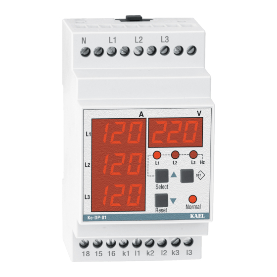
ke-DP01
Digital Protector
Voltage – Current
and
Frequency control
AREAS OF OPERATION:
■ In-Elevator motors protection
■ On-pump and electric motor
■ Resistance in oven w ith
Ge neral:
In three phase systems, it measures RMS values of AC voltages,
currents and system frequency sensitively. Using up direction button
(Select) phase-neutral voltages and phase-phase voltages monitor
sequentially.
ke-DP01 has many features.
Those are;
- Phase Failure
- Phase Sequence
- Over Voltage Protection
- Under Voltage Protection
- Voltage Unbalance (asymmetry) Protection
- Over Current Protection
- Under Current Protection
- Current Unbalance (asymmetry) Protection
- Over Frequency Protection
- Under Frequency Protection
When device is turn on if its adjusted voltages and frequency in its
interval and if phase sequence is correct relay sw itch on.
If any of error occurred ( except phase failure and phase sequence )
at the end of adjusted time relay sw itch off its contact. When system
return normal values, at the end of time out relay sw itch on.
IM PORTANT: L1 - N is device supply inputs. Thus,the applied L1 – N
voltage must be rated voltage of system . Otherw ise normal led
makes flash and the device sw itched off its output contact.
The measured frequency also must the frequency of the system.
Phase Failure: (u-U)
Before starting system , it controls phase absence then if all phases
exits Normal LED turn on and relay contact sw itch on. In case of
missing of any L1,L2,L3 phases , Normal LED turn of f and relay
sw itch off its contact .In this case
L1
L2
L3
Re
< t-1
V
V
V
,
L1
L2,
L3
V
V
V
L12,
L23,
L13
I
I
I
L1,
L2,
L3
Hz
Phase Sequence Control
Over Voltage Protection
Under Voltage Protection
Unbalanced Voltage
Protection
Over Current Protection
Under Current Protection
Unbalanced Current
Protection
Over Frequency
Protection
Under Frequency
Protection
Latch Function
TRUE RM S
(se q)
(se q)
(o - U)
(u - U)
(unb)
(o - C)
(u - C)
(ubC)
(o - F)
(u - F)
u-U
w arn appears on display.
t-1
Display Functions :
V
L1
L1
L2
L3
V
L2
L1
L2
L3
V
L3
L1
L2
L3
V
L12
L1
L2
L3
V
L23
L1
L2
L3
V
L13
L1
L2
L3
Phase Sequetion: (Seq)
In case of w rong phase order , Normal LED turned off and relay
contact is not sw itch on. In this case
screen. If phase order is corrected , Normal LED turned on and out
relay sw itch on.
L1
L1,L2,L3
L1,L3,L2
L2
L3
Re
Voltage Unbalanced: (unb)
The phase-phase voltage unbalance limit can be adjusted betw een
(5% - 20%) . When it exceeds the adjusted limit , the device
sw itched off its out contact at the end of t-1 delay. In this case
unb
w arn appears on the screen. For the returning normal state,
asymmetry values should under 20% (hysteresis value). In this
case at the end of t3 time Normal LED turned on and output contact
sw itch on. If the phase-phase voltage unbalance, return adjusted
value shorter than t-1 time, output relay does not release its
contact. Hysteresis is 20 %.
unb = 000(oFF) protection is disable .
Exam ple: Let's say that asymmetry value is set to %15 for a
3 x 380VAC.
In this case, relay contact sw itch off at (380-(380x0.15))=323 V.
Sw itch on the contact is performed at 323+(380x%15x%20)= 334V.
(%20 is the hysteresis).
(V
- V
)
max
min
% unb =
x 100
380
+ % unb
hy s
V
nom
hy s
- % unb
Lev el
Re
r-t
Spe cial Buttons :
Se lect: (Up direction)
w hen pressing continuously,
screen displays frequency of
system. When button release
device continue to show voltage.
Re s et:
If error case although disappeared
then device is not return to normal,
latch-function occurred and it
makes locked device.
Or Lock-function (only for
currents) may be occured.
After checking error in system
then restart device w ith pushing
reset button.
seq
w arn appears on the
L1,L2,L3
L2,L3
Hys = 380 x (% Asm) x (% 20)
< t-1
t-1
r-t
1
t-1
Advertisement

Related Manuals for KAEL ke-DP01


Summary of Contents for KAEL ke-DP01
- Page 1 Using up direction button screen. If phase order is corrected , Normal LED turned on and out (Select) phase-neutral voltages and phase-phase voltages monitor relay sw itch on. sequentially. ke-DP01 has many features. L1,L2,L3 L1,L3,L2 L1,L2,L3 L2,L3 Those are;...
- Page 2 Ove r and Unde r Voltage : (o-U),(u-U) 2.6 Asym m e tric Current Prote ction: Under voltage (u-U) it can adjusted betw een Umin= (300 – 370 V). It can be set by the user betw een 5% and 40%. It controls the Over voltage (o-U) it can adjusted betw een Umax=(390 –...
- Page 3 ACCESSING PARAM ETER M ENU: Push the SET button during 3 seconds. Current transformer Accessing Primer value Current Parameter 005 – 000 A ( 5 – 1000 ) A Over Voltage Over Current Accessing ( o – U) ( o – C) Voltage phase - phase Parameter...
- Page 4 Connection : TECHNICAL INFORM ATION: Rated Voltage (Un) : 220Vac (L1-N) Operating Range : (0,8-1,1) x Un Frequency : 50 / 60 Hz Supply Pow er Consumption : < 4VA Current Transformer Ratio : X / 5A Current Measurement Range : (for seconder current) 0,05 - 6 Amp AC Voltage Measurement Range : (Phase-Phase)10 - 500 Vac, 45 - 65Hz : (Phase-Neutral )10 - 300 Vac, 45 - 65Hz...
Need help?
Do you have a question about the ke-DP01 and is the answer not in the manual?
Questions and answers