Table of Contents
Advertisement
Quick Links
Advertisement
Table of Contents

Summary of Contents for PoLabs PoScope Mega1+
- Page 1 PoScope4 USER MANUAL PoScope4 Version 2.4...
-
Page 2: Table Of Contents
POSCOPE4 AND MEGA1+ MANUAL CONTENTS QUICK START GUIDE ..........................3 INTRODUCTION ............................4 PoScope4 measurement package ......................6 HARDWARE CONNECTIONS ........................8 Top view .............................. 8 Front view ............................8 Back view ............................. 8 PINOUT ASSIGNMENT ......................... 9 INPUTS AND OUTPUTS ........................9 SOFTWARE INSTALLATION ........................ -
Page 3: Quick Start Guide
POSCOPE4 AND MEGA1+ MANUAL QUICK START GUIDE STEP 1 STEP 2 DOWNLOAD AND INSTALL SOFTWARE PLUG IN YOUR DEVICE STEP 3 STEP 4 ATTACH PROBE TO YOUR DEVICE START USING YOUR DEVICE www.poscope.com... -
Page 4: Introduction
POSCOPE4 AND MEGA1+ MANUAL INTRODUCTION Dear customer! Thank you for choosing our products. We prepared this handy manual for you to get to know your new device a little better. Enclosed, you will find your PoScope Mega1+ device. Bundle package also contains: PoProbe 60 (60 MHz probe), ... - Page 5 Our youtube channel provides an access to many tutorials on how to use your device and software. Visit us on youtube: www.youtube.com/poscopelabs If you still encounter any difficulties with the device or you have further questions, please don’t hesitate to write us to support@polabs.com. Best regards, PoScope TEAM www.poscope.com...
-
Page 6: Poscope4 Measurement Package
POSCOPE4 AND MEGA1+ MANUAL POSCOPE4 MEASUREMENT PACKAGE PoScope measurement package consists of: PoScope hardware (Mega1, Mega1+, etc.), PoScope4 software, PoScope4 plugin (Mega1, Mega1+, etc.) www.poscope.com... - Page 7 POSCOPE4 AND MEGA1+ MANUAL Mega1+ is connected to a PC via USB cable. On the PC there is installed PoScope4 measurement software and one part of the PoScope4 application is device plugin. Device plugin has its own graphical interface which is used to configure and control the hardware (Mega1+, etc.). Graphical interface of plugin looks like a dashboard of a physical oscilloscope.
-
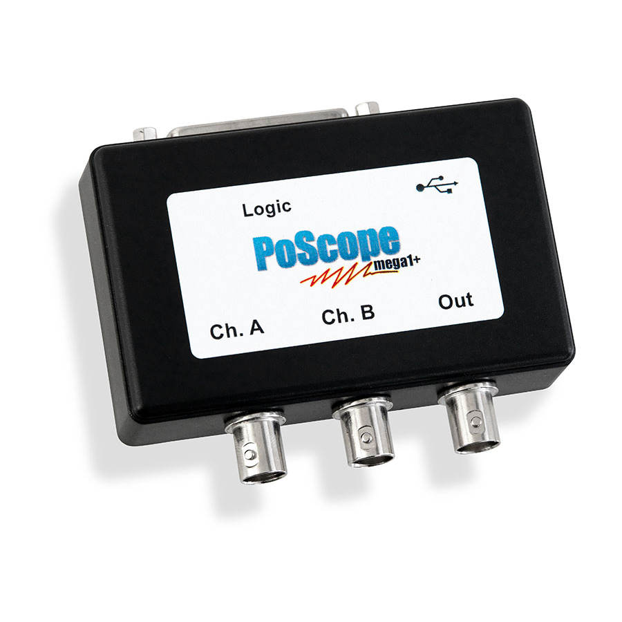
Page 8: Hardware Connections
POSCOPE4 AND MEGA1+ MANUAL HARDWARE CONNECTIONS Top view Front view Back view LOGIC ANALYZER USB PORT www.poscope.com... -
Page 9: Pinout Assignment
POSCOPE4 AND MEGA1+ MANUAL PINOUT ASSIGNMENT INPUTS AND OUTPUTS www.poscope.com... -
Page 10: Software Installation
POSCOPE4 AND MEGA1+ MANUAL SOFTWARE INSTALLATION MINIMUM SYSTEM REQUIREMENTS RESOLUTION 1024 X 768 @ 24-BIT MEMORY 512 MB PROCESSOR 1 GHZ OPERATING SYSTEM MS WINDOWS XP SP3 CONNECTION 1 FREE USB SLOT HARD DISK 50 MB (SOFTWARE) + RECORDER DATA NETWORK WORKING INTERNET CONNECTION (SOFTWARE &... - Page 11 POSCOPE4 AND MEGA1+ MANUAL Follow on-screen instructions & go throught PoScope installation procedure. It is advised to close all other programs at this point of the installation. It is advised to remove the old version before proceeding, if you have one installed. Leave the tick in the checkbox.
- Page 12 POSCOPE4 AND MEGA1+ MANUAL Package selection window lets you choose which program features to install. If you don’t plan to use other devices in near future, you can deselect them by clicking the checkbox next to it. You can always install it later, if needed.
- Page 13 POSCOPE4 AND MEGA1+ MANUAL You can make the shortcut for PoScope available to all users or just to the currently logged Administrator. Installation window summarizes the installation settings; installation folder & shortcut name. If everything is OK, you’re ready to go. Click next.
- Page 14 POSCOPE4 AND MEGA1+ MANUAL Please wait until the setup installs all the files to your PC. Setup window informs you about the device driver installation. No settings needed, just click next. www.poscope.com...
- Page 15 POSCOPE4 AND MEGA1+ MANUAL Green tick means that device drivers are installed and the device is ready for use. Click finish. You are being informed about the successful installation of PoScope software with drivers. We are ready to move on & learn how to use the installed software.
-
Page 16: Software Manual
POSCOPE4 AND MEGA1+ MANUAL SOFTWARE MANUAL Run PoScope software: You will find PoScope shortcut under PoScope folder of your startup menu. www.poscope.com... -
Page 17: Poscope4 User Interface
POSCOPE4 AND MEGA1+ MANUAL PoScope4 user interface PoScope4 user interface consists of the following items: Main menu Device displays Analyze / Capture button Device plugins Event log Main menu is organized into tabs. Device displays open new windows which represent various oscilloscope functions. Analyze / Capture button is used to switch between the Analyze and Capture mode. -
Page 18: Organize Your Desktop
POSCOPE4 AND MEGA1+ MANUAL Organize your desktop The Desktop tab lets you manage your work area – the desktop. You can freely organize the displays that are open in work area and save their configuration as a desktop file, so you don’t have to organize them every time you restart the PoScope 4 application. - Page 19 POSCOPE4 AND MEGA1+ MANUAL General tab will allow you to: o Invert mouse scroller function (zoom on forward / backward scroll) o Choose between Classic or Dynamic layout (Classic layout keeps the Device displays in the frame of main application, while the Dynamic layout lets you freely move Device displays even over multiple monitors) o Change user interface language (English, Portugese, Slovenian, Polish and Dutch are currently available)
- Page 20 POSCOPE4 AND MEGA1+ MANUAL Fonts are also fully configurable. Find the fonts settings under the Settings tab. The Fonts dialogue box lets you configure the size of the fonts for each application segment. Font size user interface www.poscope.com...
- Page 21 POSCOPE4 AND MEGA1+ MANUAL You can set the number of connected devices in the device instances tab. Device instances setup www.poscope.com...
-
Page 22: Device Displays
POSCOPE4 AND MEGA1+ MANUAL On our website you can find latest release of the PoScope software and new PoLabs devices, including the PoScope oscilloscopes and PoKeys controllers. YouTube channel provides installation and video tutorials on how to use the PoScope devices. - Page 23 POSCOPE4 AND MEGA1+ MANUAL Device displays before using the align function Device displays after using the align function www.poscope.com...
- Page 24 POSCOPE4 AND MEGA1+ MANUAL Dynamic layout is also available. You can set it in the settings menu. The Device layout lets you place Device displays also outside the main application, therefore it might come handy when multiple monitors are connected to the workstation. Device displays outside the main application in Dynamic mode www.poscope.com...
-
Page 25: Mega1 Controls
POSCOPE4 AND MEGA1+ MANUAL Mega1 controls Each of the devices that you can use in the PoScope 4 environment, has its own dedicated controls. Since they are plug & play enabled, we call them plugins. Once connected, you can open the Mega 1 controls with a click on its icon. - Page 26 POSCOPE4 AND MEGA1+ MANUAL PoScope Mega1 Plugin (digital mode) Poscope Mega1 Plugin (analog mode) The color of graphic signal representation of each channel is also customizable by clicking the color square next to each channel. Waveform color settings www.poscope.com...
-
Page 27: Oscilloscope
POSCOPE4 AND MEGA1+ MANUAL OSCILLOSCOPE Oscilloscope is an electronics measurement device that visually represents an electric signal, either alternating or direct current (AC or DC). An oscilloscope graphically shows variations of voltage. As such it is appropriate for measuring and analyzing fast changing electric signals. For this example we connected the analog generator output to oscilloscope channel A of the same Mega1 device. - Page 28 POSCOPE4 AND MEGA1+ MANUAL You might come across the message: Device not in analog mode. In that case you will have to open the device controls and switch the device back to analog mode in the DAQ section. ‘’Device not in analog mode!’’ Error message Device controls –...
- Page 29 POSCOPE4 AND MEGA1+ MANUAL Capture mode A window will open, showing graphical representation of a measured signal. To expand the timebase, find the magnifying glass icons in the bottom left corner of the oscilloscope display. Magnifying glass icons for timebase setting www.poscope.com...
- Page 30 POSCOPE4 AND MEGA1+ MANUAL After expanding the timebase you will get far better graphical presentation of the observed signal. To view the controls of the device, you have to click the device buttons area of the GUI. To view the plugin controls of oscilloscope PoScope Mega1+, left-click the PoScopeMega1 button.
- Page 31 POSCOPE4 AND MEGA1+ MANUAL Since the analog generator outputs a voltage amplitude of no more than 2V, you can set the channel A knob to 2V. You will get graphical representation shown below. Some signals change very fast. To catch the desired event, you can use triggering. Trigger is a standard oscilloscope function that allows you to catch the live signal at some particular point so you can closely analyze it.
- Page 32 POSCOPE4 AND MEGA1+ MANUAL When you’re done with capturing the signal, you can closely examine it. Click Analyze in the top-right corner of the PoScope4 software. Waveform will freeze. www.poscope.com...
- Page 33 POSCOPE4 AND MEGA1+ MANUAL Analyze mode When pressing analyze additional control with yellow colored selector appears on the top of the waveform. This control is called analyze overview and its purpose is to give users the idea of overall content of data in buffers for further analysis. Data displayed on overview control is ordered by time so the oldest data is left-most and most recent data is right most.
- Page 34 POSCOPE4 AND MEGA1+ MANUAL To read the amplitude of the signal, you don’t have to constantly calculate the Volts/div X number of divisions. Just use the 2 vertical cursors available, C1 and C2. Find them in your oscilloscope window, click & drag to desired position. Below you will find Data table command. It opens small table with current values of voltage amplitude and time difference between C1 and C2.
- Page 35 POSCOPE4 AND MEGA1+ MANUAL If you click with left mouse button in the data table you can toggle between time calculation between two cursors and frequency calculation. In the right-bottom corner you can see estimated frequency calculation. It's an estimation and its accuracy depends on your sampling frequency setting and your signals applied at the inputs.
- Page 36 POSCOPE4 AND MEGA1+ MANUAL Oscilloscope 12-bit sampling www.poscope.com...
- Page 37 POSCOPE4 AND MEGA1+ MANUAL If needed, you can export the measured data to external file. Filter out data of interest (channel A, B) and current chart / selected buffer range, and then click Export. Supported file types are: .csv, .xls, ...
-
Page 38: Mega1+ Sampling Frequency (Analog And Digital Daq Mode)
POSCOPE4 AND MEGA1+ MANUAL Mega1+ sampling frequency (analog and digital DAQ mode) If you change sampling frequency knob you will note that label under the knob is changing from Pipe to Buffer. Pipe and Buffer are names for two different data transfer modes. Data is transferred over full speed USB 2.0 which has speed limitations (1,5Mb/s theoretical). -
Page 39: Using Multiple Devices In Poscope4
POSCOPE4 AND MEGA1+ MANUAL Using multiple devices in PoScope4 Sometimes there is a need to measure more than 2 analog signals. PoScope4 can load a number of different plugins (different oscilloscope devices) and also provides multiple instances of same plugin (same oscilloscope devices). -
Page 40: X/Y Scope
POSCOPE4 AND MEGA1+ MANUAL X/Y SCOPE There are applications where we need to know phase differences between two or more varying voltages. Oscilloscope can be used to track phase differences between multiple input signals. X/Y scope plots them out as one voltage versus another. If input signals are periodic resulting curves are called Lissajous figures. - Page 41 POSCOPE4 AND MEGA1+ MANUAL You might come across this window. In order to track phase differences, both of the channels have to be active. You have to turn on the signal on channel B on the Mega1 device plugin controls. ‘’One of the channels is not active’’...
- Page 42 POSCOPE4 AND MEGA1+ MANUAL In order to see the phase differences, you can open oscilloscope display and enable the trigger function on one of the channels. One of the signals will freeze, the other will move across the display in relationship to the first one. XY mode with trigger function Now let’s draw some basic Lissajous curves.
- Page 43 POSCOPE4 AND MEGA1+ MANUAL When we change the ratio to 1:2, for instance to 10Hz on channel A and 20Hz on channel B, the figure 8 rotates to 90° and we get this infinity symbol. At greater ratios we just get more twists. Lissajous curves figure infinite at frequency ratio 1:2 When there is 90°...
- Page 44 POSCOPE4 AND MEGA1+ MANUAL Source signals for X/Y scope displayed on Oscilloscope. Let’s add X/Y scope and select as a source device with periodic sine waves mentioned before. X/Y or Channel A / Channel B representation would look like on a picture below. X/Y scope for periodic input signals.
-
Page 45: Spectrum Analyzer
POSCOPE4 AND MEGA1+ MANUAL SPECTRUM ANALYZER Spectrum analyzer measures signal amplitude over wide range of frequencies. It plots a waveform of signal amplitude (Y axis) against frequency range (X axis). With spectral analyzer you can find out the dominant frequency of a known signal and the amplitude / frequency of the unknown or undesired signals, as well as signal’s other spectral components (power, distortion, harmonics, bandwidth, etc.) PoScope4 uses Fast Fourier transformation (FFT) for a frequency analysis of an electric signal. - Page 46 POSCOPE4 AND MEGA1+ MANUAL Waveform below shows frequency spectrum of periodic signal coming from analog generator. Frequency of the signal is set to approximately 10 kHz. Waveform is being plotted as signal amplitude (Y axis) vs. frequency (X axis). Clicking Axes gives you additional set of settings to examine frequencies of the input signal.
- Page 47 POSCOPE4 AND MEGA1+ MANUAL In the Frequency analyzer, cursors are also available. Drag and drop them with your mouse to find out which frequencies are most dominant. To view the relationships between C1 and C2, click on the data table. Frequency analyzer with data table open www.poscope.com...
- Page 48 POSCOPE4 AND MEGA1+ MANUAL Click on Analyze button will take you to Analyze mode. In analyze mode the overview control will open. You can resize the yellow selector by hovering your mouse over it and use the scroll wheel to make the yellow square smaller.
-
Page 49: Recorder
POSCOPE4 AND MEGA1+ MANUAL RECORDER Analyze button is limited with the amount of RAM memory installed in a workstation where measurements are taken. To avoid the limits of RAM memory, you can save measurements to an external file on your disk. Therefore the total amount of measuring samples will be limited with the total capacity of your hard drive, SSD or USB drive. - Page 50 POSCOPE4 AND MEGA1+ MANUAL Measurement samples can be recorded to PoScope4 recorder file or PCM file (pulse-code modulated data). PCM is intended for use in 3 party software, therefore it can’t be open in PoScope4 application. Recording to PCM will create additional txt header file with following info: number of channels, ...
- Page 51 POSCOPE4 AND MEGA1+ MANUAL Once open, you can switch pages and resize the overview selector. If you hover over the waveform you can change the timebase using mouse scoller and drag the waveform left and right using you left mouse button. Data table and export features are also available as in the oscilloscope display. www.poscope.com...
-
Page 52: Logic Analyzer
POSCOPE4 AND MEGA1+ MANUAL LOGIC ANALYZER Logic analyzer is an electronic measurement instrument, capable of capturing and displaying multiple signals from a digital circuit. With this powerful tool you can observe many digital signals at the same time and perform exact time measurements. It is useful for various tasks in electronics design, testing and repair: analyze timing errors, ... - Page 53 POSCOPE4 AND MEGA1+ MANUAL Run the Logic Analyzer by clicking its icon in the Displays tab of PoScope4 software: Below you can see an example of displaying digital ports of a PoKeys input / output device. As in oscilloscope mode, you can click Analyze button to closely view the captured data. Logic analyzer waveforms www.poscope.com...
- Page 54 POSCOPE4 AND MEGA1+ MANUAL When in Analyze mode, use the yellow selector above to select the part of captured data for even closer observation. Resize the yellow selector with scroll wheel and drag it to point of interest. Logic analyzer in Analyze mode with Overview window open On the right side of the Logic analyzer display you will find 2 tabs.
- Page 55 POSCOPE4 AND MEGA1+ MANUAL When done, you can hover over the part of the certain square waveform to see additional details. You can export the data selected in overview window to an external file in various formats. Logic analyzer export settings www.poscope.com...
-
Page 56: I2C Decoder
POSCOPE4 AND MEGA1+ MANUAL I2C DECODER Inter – integrated circuit simplifies the hardware part of electronic devices. It consists of only 2 wires. One is used for clock synchronization, the other one is for data transfer purposes. On each I2C bus you will find one master and multiple slaves. - Page 57 POSCOPE4 AND MEGA1+ MANUAL Use the overview yellow selector and mouse scroller to select part of data for analysis and decoding. Pin that has most dense pulses is usually the clock. You can also rename Pin by double-clicking its name. The second pin is data. I2C decoder clock (SCL) and data (SDA) lines To add I2C decoder, click the + button on the I2C pane under Decoders tab.
- Page 58 POSCOPE4 AND MEGA1+ MANUAL I2C Settings window Under the View, you can select how you want the decoded data to be shown. HEX, DEC, CHAR, BIN, HEX & CHAR, DEC & CHAR are available. Measurements can be shown in the side panel or as a hint when you hover the mouse cursor over the I2C data.
- Page 59 POSCOPE4 AND MEGA1+ MANUAL Decoded I2C packages in Logic analyzer display In the display window you can see: The start bit, Master read initialization, The address master wants to read from, The acknowledge bit, The transferred data and ...
-
Page 60: Function Generator (Only For Mega1+ Devices)
POSCOPE4 AND MEGA1+ MANUAL FUNCTION GENERATOR (Only for Mega1+ devices) Function generator is capable of generating different types of periodical electrical waveforms over a wide range of frequencies, limited to 12,5kHz. It can generate sine, square, triangle and saw, showed below. Function generator can be used in development, test and repair of electronic equipment, e.g. - Page 61 POSCOPE4 AND MEGA1+ MANUAL To show you the basic use of function generator, we connected two probes to the PoScope Mega1+, first one to the function generator output and the second one to oscilloscope channel A. We connected the signal and the ground connections of the two probes and ran the function generator at 5 kHz.
- Page 62 POSCOPE4 AND MEGA1+ MANUAL Find the analog generator controls on the right half of the Mega 1 plugin. Besides shape of the signal (sine, square, triangle, saw) and its frequency (limited to 12.5 kHz) you can also set its amplitude, expressed in % of 1.8Vpp.
- Page 63 POSCOPE4 AND MEGA1+ MANUAL Function generator square waveform Function generator triangle waveform www.poscope.com...
- Page 64 POSCOPE4 AND MEGA1+ MANUAL Function generator saw waveform www.poscope.com...
-
Page 65: Technical Specifications
POSCOPE4 AND MEGA1+ MANUAL TECHNICAL SPECIFICATIONS Oscilloscope No. of channels 2 channels Sample rate 1.0 MS/s (dual channel) 2.5 MS/s (single channel) Input voltage -20 V … +20 V WARNING: Do not connect the oscilloscope to voltages higher than specified. ADC resolution 12 bits Triggering... -
Page 66: Legal Notes
PoLabs devices may be used in equipment that does not impose a threat to human life in case of the malfunctioning, such as: computer interfaces, office equipment, communications equipment, test and measurement equipment, audio and visual equipment, home electronic appliances, machine tools, personal electronic equipment, and industrial robots. -
Page 67: Grant Of License
PoDDS, PoScope, PoLabs and others are internationally registered trademarks. GRANT OF LICENSE The material contained in this release is licensed, not sold. PoLabs grants a license to the person who installs this software, subject to the conditions listed below. Access The licensee agrees to allow access to this software only to persons who have been informed of and agree to abide by these conditions. - Page 68 POSCOPE4 AND MEGA1+ MANUAL Fitness for purpose No two applications are the same, so PoLabs cannot guarantee that its equipment or software is suitable for a given application. It is therefore the user's responsibility to ensure that the product is suitable for the user's application.
Need help?
Do you have a question about the PoScope Mega1+ and is the answer not in the manual?
Questions and answers