Table of Contents
Advertisement
Quick Links
www.ens-sys.co.kr
Automotive diagnostic Equipment for noise and vibration
Easy Check for Vehicles
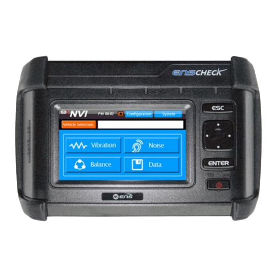
NVB-150 helps you to find noise and vibration problems quickly and easily with any vehicle.
NVB-150 provides the maintenance standards by measuring vibration.
NVB-150 helps you to control vehicle balance by measuring vibration and rotation of a propeller shaft.
NVB-150 is easy to use for everyone
www.ens-sys.co.kr
NVB-150 User Manual
Table of Contents
3
4
5
7
9
10
11
11
12
13
2
NVB -150 User Manual
15
15
18
20
21
28
35
47
52
55
59
NVB -150 User Manual
Advertisement
Table of Contents

Summary of Contents for ENS NVB-150
-
Page 1: Table Of Contents
NVB-150 provides the maintenance standards by measuring vibration. NVB-150 helps you to control vehicle balance by measuring vibration and rotation of a propeller shaft. NVB-150 is easy to use for everyone NVB -150 User Manual www.ens-sys.co.kr... -
Page 2: General Information
ENS SYSTEM is not responsible for use in any application other than the measuring purposes. ENS SYSTEM is not responsible for damages due to improper operation, maintenance, connection to improper voltage supply, or attempt to repair by anyone other than a facility authorized by ENS SYSTEM. -
Page 3: Product Features
3. Product Features Measuring noise Measuring vibration Propeller Shaft Balancing Product Specifications Dimension 200mm(W) X 150mm(H) X 30mm(D) Weight 512g Operating System Windows CE 5.0 Voltage Use 220V to 12V (Use Voltage Adapter) Input Voltage Power Consumption... -
Page 4: Nvb-150
4. NVB - 150 4-1. NVB-150 and accessories Vibration Sensor NVB-150 Vibration Sensor (Top Type) (Side Type) Noise Sensor (MIC) Sensor Holder ( Magnetic Mount) RPM Sensor(Photo Sensor) NVB -150 User Manual www.ens-sys.co.kr NVB-150 Noise Sensor Cable Photo Tacho Sensor Cable... -
Page 5: Installing Sensor
According to environmental condition, sensitivity may change. Sensor must be checked periodically(6~12month). NVB -150 User Manual www.ens-sys.co.kr NVB-150 3) Photo Sensor (Rotational speed Sensor) Install the Photo sensor pointed to the reflective tape. Reflective tape must be located in the P/Shaft. -
Page 6: Nvb-150 Operating
Power Button 1. NVB-150 has already installed a battery. Press power button for 3 seconds to turn on your NVB-150. LED will go red and system will start. 2. If your NVB-150 does not start, battery may be discharged then use the AC Power Adapter. -
Page 7: Operating Function Key
6. The “Focusing State” shown above may adjust by using the Function key. 7. 4 way navigation key can be operated by using the chart on page 19. 8. 4 way navigation key provides an easy way to operate your NVB-150. NVB -150 User Manual... -
Page 8: Nvb-150 Software
6. NVB-150 Software Software Menu 6-1. Menu Main Menu Initial Screen Menu Detailed Menu Function Main Screen Select Menu Vehicle Selection, Vibration, Noise, Balance, Data, Configuration, System Vehicle Selection Select Vehicle Model, Engine, Transmission Location Select Channel Configuration Screen... -
Page 9: Display
UI Display 6-2. Display 6-2-1. Display Area Navigation Area 1. NVB-150 Software consists of 4 areas :<Navigation Area>, <Tab Button Area>, <Contents Area> and <Start Button Area>. Tab Button Area 2. <Navigation Area> shows where you are now. 3. <Tab Button Area> helps you to proceed to the next step. -
Page 10: Vehicle Selection
UI Display 6-2-2. Display Component elements < Function Adjustment Screen> < Keypad screen> < Main Screen> Main Function Button Tab Button Information Area Approve/ Cancel Button Time Information Start Button Keypad(digits, English) Battery Information ESC Button Keypad Shift Button Main function Button allows you to start a function which you selected from the top menu. -
Page 11: Measuring Vibration
6-4. Measuring Vibration Vibration 6-4-1. Selecting Location Select a channel. From ch1 through ch4 buttons work as a toggle mode. -> Channel ON : Green -> Channel OFF : Gray Check sensor whether connected in right channel. - Page 12 Vibration 6-4-2. Current Information and Start Measuring The screen on the left shows the current information. Press the “Start” button to start measuring. Sensor can be adjusted by pressing the <Configuration> Button. Selected information remains unchanged even if the menu is changed.
- Page 13 Vibration Screen can be converted by pressing <Cancel> or <Config.> button while processing. Measurement Information screen can be shown by pressing the <Cancel> button. <Config.> button allows you to move to Configuration Menu. <Next > button will only operate when Overload State.
-
Page 14: Measuring Noise
Vibration Each channel can be selected by pressing the <CH>Tab. Select other channels, then recalculating will be processed. Press the <Save> button to save your data. File name will be given as shown below. “TYPE_MODEL_LOCATION_YYMMDD_HHMM.nvh”... - Page 15 Noise Press the “View image” button to see a selected image. You should make sure whether sensor in right place or direction. Explanation of Abbreviation Abbreviation Part Abbreviation Part View Measuring Point EngRoom Engine Room PsgRoom Passenger Room NVB -150 User Manual www.ens-sys.co.kr...
- Page 16 Noise 6-5-3 Measuring Progress Screen Measuring Progress displays time, sensor signal and overload through input signal. Level meter will be fully increased at first then start to decrease. Level meter moves followed by the signal strength. ...
- Page 17 Noise 6-5-4 Result Screen Result Screen allows you to see the Guideline which based on acquired data. The orange colored channel tab shows result value. The gray colored channel tab indicates unused channel. Displays the level for each channel.
-
Page 18: Measuring Balance
Balance 6-6. Measuring Balance 6-6-1. Selecting Measuring Point Please, select a channel. From ch1 through ch4 buttons work as a toggle switch. When the channel lit green, which means channel is ON. When the channel lit gray, which means channel is OFF. - Page 19 Balance 6-6--2. Current Information and Start Measuring The screen on the left shows the current information. Use the “start” button to measure or Use the “config.” button to calibrate the sensor. Vehicle information can be changed from vehicle selection Menu.
- Page 20 Balance 6-6-4 Measuring Mode If standard DB is applied to your NVB-D150V, process has two modes : [DB Vehicle Measuring Mode] and [User Measuring Mode] Each mode will be separated automatically when choosing a vehicle and engine. Selecting Measuring Point [DB Vehicle Measuring Mode] : P/Shaft desired RPM is already set.
- Page 21 Balance 2. Measurement Failure and Over Load State Continue your progress until desired PRM reaches the 5 Sec. Press the “Cancel” button to cancel the measurement. A letter changes to red color when the vibration sensor becomes the “Over Load”...
- Page 22 Balance Pay attention to Weight and Target Angle of diagnosis result. 4. Diagnosis result Angle indicates that location of reflective tape increases clockwise based on 0 degree. Make sure you must check the rotational direction when you calculating Angle.
- Page 23 Balance 2. STEP1 Measuring Measuring will be successfully completed when P/shaft RPM maintains for 5 Sec as desired RPM. When measuring is complete, system will automatically move to next screen. ▶ Press the “Cancel” button to return to the Start Screen.
-
Page 24: Saving Data
Data 6-7. Saving Data 6-7-1. File Management File Management allows you to manage files. 1. Selecting Data Type Data Management allows you to check stored information. Select the Data Type by pressing an arrow button. Data List Data Type Selected information can be changed by using ←... - Page 25 Data 6-7-2. Open Vibration Diagnostic Data Playback Data Screen Data Screen indicates user inputs and condition. Channel indicates measurement location. Press the <Next> button to display diagnostic value. Press the <List> button to display data management screen.
-
Page 26: Configuration (For Measuring)
Data 6-7-4. Open Balance Diagnostic Data Data Screen 4 Pts Data Screen indicates user inputs and condition. Channel indicates measurement location. Press the <Next> button to display diagnostic value. Press the <List> button to display data management screen. - Page 27 Configuration 2. Setting RPM & Frequency Desired RPM displays the number of rotations of P/Shaft to be maintained when measuring the balance. Desired RPM is set for “3500” Setting the RPM Frequency setting is range of frequencies.
-
Page 28: System Configuration
System 6-9. System Configuration The system configuration sets up functions of the NVB-150. Sets the date and time, LCD contrast, and volume. To update your software, Please visit our website. 6-9-1. Volume Use the (+) and (-) buttons to adjust the volume. - Page 29 After downloading, update can be started. For OS Update, please use your NVB-150 Unit. After update has been completed, please restart your system. For S/W update, software can be downloaded onto your SD Card without using the Updating NVB-150 Unit.
-
Page 30: Warranty
Warranty 1. ENS SYSTEM will supply, at no charge, new or rebuilt replacements in exchange for defective parts for a period of one (1) year. 2. This warranty covers all defects encountered in normal use of the NVB-150, and does not apply in the following cases : -This warranty does not cover damage due to acts of God, accident, misuse, abuse, negligence, or modification of, or to any part of the Product.
Need help?
Do you have a question about the NVB-150 and is the answer not in the manual?
Questions and answers