Advertisement
Quick Links
Advertisement

Related Manuals for Stac Zero Powermeter

Summary of Contents for Stac Zero Powermeter
- Page 1 Powermeter Upgrade Manual Rev 3.0...
-
Page 2: Table Of Contents
Welcome to the world of power training! Congratulations on purchasing your STAC Zero Powermeter upgrade! You will now be able to track your progress with real numbers, and make use of online training apps. In our experience, training with the Powermeter has led to substantial improvements in performance. -
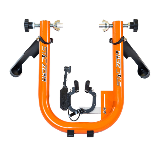
Page 3: Upgrade And Trainer Components
UPGRADE AND TRAINER COMPONENTS UPGRADE KIT POWERMETER STRAIN GAUGE SET SCREW WIRE MAGNET SENSOR 2 SCREWS TRAINER COMPONENTS RESISTANCE UNIT: MOUNTING BOLTS QUICK RELEASE CALIPER MAGNET ARRAY MAGNETS ALUMINUM BEAM... -
Page 4: Upgrade Steps
3mm Allen Key until they extend past the Strain Gauge by at least 2 threads. Figure 1 2) Undo the two Mounting Bolts using a 4mm Allen key (included with your original STAC Zero purchase) and remove the Resistance Unit from the Frame (Figure 2). Figure 2... - Page 5 3) Set up: Rotate the Magnet Array to the open position. Loosen the Quick Release slightly so the Calipers can be moved by hand Open the Calipers and place the Resistance Unit face down on a flat, non-magnetic surface (Figure 3). Note: This allows you to remove the Beam from the Quick Release without the Magnets snapping...
- Page 6 6) Snap the plastic casing of the Powermeter onto the Caliper that is directly touching the Strain Gauge. Align the screw holes and tighten the screws using a 5/32” Torx screwdriver (Figure 5). Figure 5 7) Remount the Resistance Unit on the Frame with the Mounting Bolts (Figure 6).
-
Page 7: Wheel Magnet Alignment
WHEEL MAGNET ALIGNMENT Support Video: “Wheel Magnet Alignment” Due to some slight variation, the Magnets may not be parallel to your wheel after the upgrade is executed, however this is easily adjusted. Perform this step with the bike mounted on the trainer so you can see the results of the adjustment. -
Page 8: Concentricity
CONCENTRICITY The Magnet Arrays should track the curve of the wheel when viewed from the side. If the Magnet Arrays appear concentric, proceed to the next section. If one end of the Magnet Array is higher/lower on the brake track, follow these steps. Concentric Magnet Array Non-concentric... -
Page 9: Parallelism
If a greater change in the mounting angle is necessary: a. Further loosen the opposing Mounting Bolt. b. Tighten both Set Screws to lift the Strain Gauge slightly further away from the Frame. c. Re-tighten the appropriate Mounting Bolt. 3. Ensure both Mounting Bolts are tight to secure the Resistance Unit. - Page 10 a. If the Magnet Arrays skew right towards the front of the bike when viewed from above, tighten the Set Screw closer to the arm of the Frame. Tighten b. If the Magnet Arrays skew left towards the front of the bike when viewed from above, tighten the Set Screw closer to the center of the trainer.
- Page 11 3. Re-tighten the Mounting Bolts. 4. Re-check Parallelism and Concentricity. FINAL STEPS: 1. Re-align your Spoke Magnet with the tip of the Speed Sensor. You are ready to ride!
-
Page 12: Powermeter Setup And Configuration
Rotate the wheel a couple of revolutions slowly by hand to make sure the spoke magnet will not hit your bike or the Magnet Sensor. Allow the unit to sit for 15 seconds after the Powermeter lights have activated to allow for self-calibration. - Page 13 [This page intentionally left blank]...
- Page 14 [This page intentionally left blank]...
- Page 15 Regulatory Compliance Product: STAC Zero Powermeter Model: Rigado BMD-300 FCC ID: 2AA9B04 IC: 12208A-04 European Compliance Statement STAC Performance hereby declares that this device is in compliance with the essential requirements and other relevant provisions of the R&TTE Directive. FCC Compliance This device complies with Part 15 of the FCC Rules.
- Page 16 For support go to: www.staczero.com/support For additional assistance, contact us at: support@staczero.com Looking for more speed on the bike? Check out the STAC Virtual Wind Tunnel: Improve your speed at your next race! All the benefits of wind tunnel testing without the cost and inconvenience of going to one.
Need help?
Do you have a question about the Powermeter and is the answer not in the manual?
Questions and answers