
Related Manuals for RoboMaster PM01

Summary of Contents for RoboMaster PM01
- Page 1 RoboMaster Referee System Power Management Module PM01 User Guide 使用说明 v1.0 2018.11...
- Page 2 DJI and RoboMaster are trademarks of SZ DJI™ Technology Co., Ltd and its affiliates. Names of products, brands, etc., appearing in this document are trademarks or registered trademarks of their respective owner companies.
-
Page 3: Inventory List
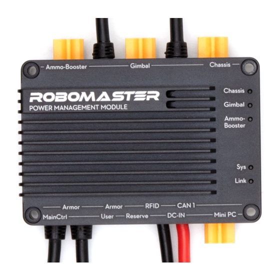
RoboMaster website to learn more about the product. Introduction The RoboMaster Referee System Power Management Module provides 24 V DC power output to the chassis, gimbal, and launching mechanism of your robot. The module monitors the current and voltage of each of the three channels and calculates power, and then turns on or off the power output according to the commands from the server. -
Page 4: Interface Description
Interface Description Name Description Name Description Armor Module Connected to the RFID Interaction Connected to the RFID SM06B-GHS-TB Armor Module, Module SM04B- Interaction Module, interface (6-pin supplies power to it, GHS-TB interface supplies power to it, socket) and communicates with (4-pin socket) and communicates with it. -
Page 5: Dimensions And Installation
Dimensions and Installation Properly secure the Power Management Module to your robot using four M2.5 screws according to the size and distance of the mounting holes of the Power Management Module as shown in the figure. Unit: mm... - Page 6 Light Status Description The Power Management Module has five indicators in total from top to bottom: chassis indicator (which indicates the status of the power supply to the chassis), gimbal indicator (which indicates the status of the power supply to the gimbal), ammo-booster indicator (which indicates the status of the power supply to the launching mechanism), sys indicator (which indicates the status of the Power Management Module), and link indicator (which indicates the status of connection with the main controller).
-
Page 7: Product Parameters
500 ms) Total of the above 20 A (maximum continuous load) 3 channels Mini PC 6 A (maximum continuous load) Power Consumption Static no-load power consumption: 2.2 W WWW.ROBOMASTER.COM are trademarks of DJI Copyright © 2018 DJI All Rights Reserved. - Page 8 感谢您购买 RoboMaster™裁判系统电源管理模块。在使用前,请仔细阅读本声明,一旦使用,即被视为对本声明全部内 容的认可和接受。请严格遵守手册、产品说明和相关的法律法规、政策、准则安装和使用该产品。在使用产品过程中,用 户承诺对自己的行为及因此而产生的所有后果负责。因用户不当使用、安装、改装造成的任何损失,DJI™将不承担法律 责任。 DJI 和 RoboMaster 是深圳市大疆™创新科技有限公司及其关联公司的商标。本文出现的产品名称、品牌等,均为其所属 公司的商标。本产品及手册为大疆创新版权所有。未经许可,不得以任何形式复制翻印。 关于免责声明的最终解释权,归大疆创新所有。 产品使用注意事项 1. 使用前请确保连线正确。 2. 使用前请检查零部件是否完好。 3. 电源管理模块在大功率负载工况下,外壳温度偏高,请勿用手触碰。 4. 请将电源管理模块安装至通风良好的地方,避免安装于不耐热材料上,如 3D 打印材料。 5. 禁止使用 3M 胶等胶类物质固定电源管理模块。 6. 使用前,请前往 RoboMaster 官网下载《RoboMaster 2019 裁判系统用户手册》了解产品更为详细的使用功 能。 简介 RoboMaster 电源管理模块可为机器人的底盘、云台、发射机构分别提供 3 个通道 24V 的直流电源输出,监测这...
- Page 9 3 个通道的电流、电压并计算功率,然后根据服务器下发的控制指令执行电源输出通断控制操作。同时,除了为这 三路通道提供供电和检测功能外,电源管理模块还可提供 5V、12V、24V 直流电源供其他裁判系统模块使用。电源 管理模块具有通信转发功能,可将各模块发送的数据包按照要求转发至目标模块。裁判系统相关信息将可通过电源 管理模块的用户串口(User 接口)输出。 物品清单 电源管理模块 × 1 3-Pin 串口线 × 1 接口说明 1. 装甲模块 SM06B-GHS-TB 接口 (6-Pin 插座) 2. 场地交互模块 SM04B-GHS-TB 接口 (4-Pin 插 连接至装甲模块,对装甲模块进行供电,并与其通 座) 信。...
- Page 10 连接至场地交互模块,对场地交互模块进行供电, 用户信息输出接口,可于接口下方的表面丝印查看 并与其通信。 线序。 3. CAN 通讯 SM04B-GHS-TB 接口 (4-Pin 插座) 7. 系统升级 SM03B-GHS-TB 接口 (3-Pin 插座) 与场地交互模块的 4-Pin 接口具有相同功能。 系统升级接口,可于接口下方的表面丝印获取线序。 4. 主控模块接口(1 根金属圈为黑色的航空插头) 8. 裁判系统电源 XT60 输入接口 连接至主控模块,对主控模块进行供电,并与其通 24V 直流电源输入(XT60 公头) 信。 9. Mini PC 电源 XT30 输出接口 5. 其他裁判系统模块接口(3 根金属圈为银白色 Mini PC 24V 直流电源输出(XT30 母头)...
- Page 11 单位:mm 灯效说明 电源管理模块从上到下共有 5 个指示灯,分别为:Chassis 指示灯(指示底盘供电状态) 、Gimbal 指示灯(指示云 台供电状态) 、Ammo-Booster 指示灯(指示发射机构供电状态) 、Sys 指示灯(指示电源管理模块状态)和 Link 指示灯(指示与主控的连接状态) ,指示灯的具体意义如下: 信号灯 灯效 说明 Sys 指示灯 红灯每秒闪烁一次 系统正常工作 Link 指示灯 绿灯不亮 未正常连接至主控模块 绿灯闪烁 已连接至主控模块...
- Page 12 最大输出电流 Chassis(底盘) 10 A(最大持续负载) ;30 A(输出持续时间小于 500 毫秒) Gimbal(云台) 10 A(最大持续负载) ;30 A(输出持续时间小于 500 毫秒) Ammo- 8 A(最大持续负载) ;30 A(输出持续时间小于 500 毫秒) Booster ( 发 射 机构) 以上 3 通道合计 20 A(最大持续负载) Mini PC 6 A(最大持续负载) 功耗 静态空载功耗:2.2 W WWW.ROBOMASTER.COM...
- Page 13 Copyright© 2018 大疆创新 版权所有。 Contact us 联系我们 RoboMaster Website: www.robomaster.com RoboMaster BBS: bbs.robomaster.com RoboMaster Email: robomaster@dji.com...
Need help?
Do you have a question about the PM01 and is the answer not in the manual?
Questions and answers