Table of Contents
Advertisement
Quick Links
CG401S5-FCU
CG401S5V1-FCU
F
C
U
(FCU) C
AN
OIL
NIT
ONTROLLER
U
M
SER
ANUAL
V
1.2
ERSION
24 F
, 2020
EBRUARY
Disclaimers and Copyright
Nothing contained in this publication is to be construed as granting any right, by implication or otherwise, for the
manufacture, sale, or use in connection with any method, apparatus, or product covered by letters patent, or as
insuring anyone against liability for infringement of letters patent.
Efforts have been made to ensure the accuracy and reliability of the data contained in this publication; however,
CityGrow Energy Systems Limited makes no representation, warranty, or guarantee in connection with this publication
and hereby expressly disclaims any liability or responsibility for loss or damage resulting from its use or from the use
of any product or methodology described herein; for any violation of any federal, state, or municipal regulation with
which this publication may conflict; or for the infringement of any patent from the use of this publication. Nothing
contained in this publication should be viewed as an endorsement by CityGrow Energy Systems Limited of any particular
manufacturer's products.
i
Advertisement
Table of Contents

Summary of Contents for CityGrow CG401S5-FCU
- Page 1 Nothing contained in this publication should be viewed as an endorsement by CityGrow Energy Systems Limited of any particular manufacturer’s products.
- Page 2 CAUTION RISK OF ELECTRIC SHOCK DO NOT OPEN CAUTION: TO REDUCE THE RISK OF ELECTRIC SHOCK, DO NOT REMOVE COVER (OR BACK) NO USER-SERVICEABLE PARTS INSIDE REFER SERVICING TO QUALIFIED SERVICE PERSONNEL The lightning flash with arrowhead symbol within an equilateral triangle is intended to alert the user to the presence of uninsulated “dangerous voltage”...
-
Page 3: Table Of Contents
Table of content Introduction ....................1 Understanding the product ................2 Dimensions ....................3 Wiring ......................4 Installation ....................5 Application notes ..................8 6.1. Control a single FCU with a CG100HTH Thermostat ....... 8 6.1.1. Pairing procedures ..................... 8 6.2. -
Page 4: Introduction
1. Introduction Thank you for choosing CityGrow’s product. CG401S5-FCU Fan Coil Unit (FCU) Controller is highly-functional, user-friendly and installation-friendly. The CG401S5- FCU and CG401S5V1-FCU are specially designed for featuring FCU control in CityGrow’s automation system. Description ZigBee wireless remote control. -
Page 5: Understanding The Product
2. Understanding the product Cover USB Programming port Reset Test button for Temperature High/Mid/Low fan sensor speed Input AC220V Test button for cool/heat Conduit opening Main unit Connection terminals to fan coil Pin number Description 1, 2 Relay output for HEAT 3, 4 Relay output for COOL 5, 6... -
Page 6: Dimensions
3. Dimensions 152mm 56mm... -
Page 7: Wiring
WARNING! Install in accordance to all national and local electrical codes. IMPORTANT! CityGrow® is not liable for any damage incurred with the misuse of the product. IMPORTANT! Pre-setup can only be done by a professional technician or... -
Page 8: Installation
STEP 1: IMPORTANT! Turn off main power at the main switch board. STEP 2: Select a location for installation which is nearby the fan coil unit (FCU). Mount the CG401S5-FCU on the location and route the conduits. Cool, Heat, High, Mid,... - Page 9 STEP 3: Connect the wires from the FCU to the CG401S5-FCU following the below diagram. Connection terminals to fan coil Description number 1, 2 Relay output for HEAT 3, 4 Relay output for COOL 5, 6 Relay output for FAN SPEED LOW...
- Page 10 Step 5: Turn the main power on at the main switch board again. Step 6: The module is now powered up. Pressing the test button to test the module. Test button for High/Mid/Low fan speed Test button for cool/heat Step 7: Place the top cover back to the module and fasten the screws to complete the installation.
-
Page 11: Application Notes
6. Application notes CG401S5-FCU is a wireless fan coil unit controller which is able to receive signal wirelessly from CityGrow’s control plate products or thermostat. Long distance cable wiring is not required. 6.1. Control a single FCU with a CG100HTH Thermostat The signal will be sent wirelessly to the CG401S5-FCU, to control the fan speed (high, low or mid), ON/OFF and Cool/Heat mode. -
Page 12: Control A Single Fcu With Multiple Cg100Hthv1 Thermostats
“ok”, and that means the pairing process is completed. 5. If the display does not show “ok” within 2 seconds, which means the pair process is failed. Please check the power of the CG401S5-FCU and check the CG101UT5 cable. Repeat step 1 – 5 to retry again. -
Page 13: Pairing Procedures
Notes: A single CG401S5-FCU can be controlled by up to 8 units of CG100HTH Thermostat. CG100HTHV1 CG401S5V1-FCU CG100HTHV1 CG100HTHV1 Thermostat Fan Coil Control Switch Module Thermostat Thermostat To control the Fan Coil Unit (FCU) Controller with multiple CG100HTHV1 Thermostats, ONLY CG401S5V1-FCU Fan Coil Unit (FCU) Controller with inbuilt temperature sensor is applicable. -
Page 14: Pairing Procedures
Option A: Control CG401S5-FCU through inbuilt temperature sensor in CG100HTH Thermostat Option B: Control with CG100HTHV1 Thermostat through an inbuilt temperature sensor inside the CG401S5V1-FCU 6.3.1. Pairing procedures Referring to section 6.1.1, repeat step 1 to step 5 to bind the rest of the... -
Page 15: Adding The Product To Your Home Wireless Zigbee Network
USB end of the CG101UTC cable. STEP 2 Plug the CG101UTC cable into the USB port of a PC that is installed with CityGrow’s HomeNET Planner 2 Software. STEP 3 Refer to the user manual of “HomeNET Planner 2” Software to program and set the address of the product. -
Page 16: Specification
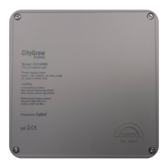
8. Specification Item Description Power supply 100-240VAC, 50/60Hz @ 80mA 5 dry contacts Loads Maximum 2A per channel @24VDC, or Maximum 4A per channel @240VAC RF frequency 2.4GHZ Remote control distance 100M (M, line of sight) 0°C to 50°C Operating temperature Operating humidity 5% to 95% non-condensing Unit Dimension L x W x D...
Need help?
Do you have a question about the CG401S5-FCU and is the answer not in the manual?
Questions and answers