Table of Contents
Advertisement
Quick Links
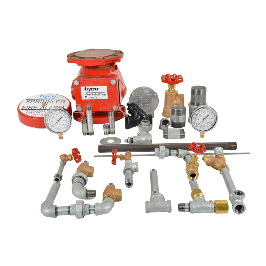
Model AV-1-300 Alarm Check Valve, 300 psi (20,7 bar)
2-1/2, 4, 6 & 8 Inch (DN65, DN100, DN150 & DN200)
Vertical or Horizontal* Installation
General
Description
The TYCO Model AV-1-300 Alarm
Check Valves are divided seat ring,
rubber-faced clapper, waterflow alarm
check valves that are intended for
use in wet pipe (automatic sprinkler)
fire protection systems. They may be
installed vertically or horizontally*,
and they are designed to automati-
cally actuate electric and/or hydraulic
alarms when there is a steady flow of
water into the system that is equivalent
to the discharge rate of one or more
sprinklers.
A separately ordered Model RC-1
Retard Chamber (Ref. Technical Data
Sheet TFP920) is required for installa-
tions subject to variable pressures. It is
used to help prevent false alarms asso-
ciated with pressure variations in public
water supplies.
The AV-1-300 Alarm Check Valve Trim
includes pressure gauges to monitor
system pressure conditions, a bypass
check valve, a main drain valve, and
an alarm test valve. The bypass check
valve reduces the possibility of false
alarms by permitting slow as well as
small transient increases in water sup-
ply pressure to be passed through to
the system without opening the water-
way clapper.
NOTICE
The TYCO Model AV-1-300 Alarm
Check Valves described herein must
be installed and maintained in com-
pliance with this document, as well as
with the applicable standards of the
National Fire Protection Association
(NFPA), in addition to the standards of
any authorities having jurisdiction. Fail-
ure to do so may impair the integrity of
these devices.
The owner is responsible for main-
taining their fire protection system
and devices in proper operating
condition. Contact the installing con-
tractor or product manufacturer with
any questions.
* 4, 6, and 8 inch (DN100, DN150, and DN200) valve sizes
Page 1 of 20
Technical
Data
Approvals
UL and C-UL Listed
FM Approved
Working Water Pressure Range
20 to 300 psi (1,4 to 20,7 bar)
Friction Loss
Refer to Graph A.
End Connections
Groove x Groove
Flange x Groove
Flange x Flange
Refer to Table A for size applicability
Weights
Refer to Table A.
Physical Characteristics
The body is ductile iron, the hand-hole
cover is ductile iron, and the seat ring
is bronze. The clapper for the 2-1/2
inch (DN65) valve size is stainless steel.
The clapper for the larger valve sizes
is ductile iron. All valve sizes utilize an
EPDM clapper facing.
Flanged connections are available
drilled per ANSI, ISO, AS, and JIS
specifications as detailed in Table B.
Threaded port connections for the
AV-1-300 Valves are available NPT
threaded or threaded per ISO 7-1 as
detailed in the Ordering Procedure sec-
tion. Valves with NPT threaded ports
will readily accept the trim arrange-
ments detailed in Figures 4 through 6.
SEPTEMBER 2014
Worldwide
www.tyco-fire.com
Contacts
For Fire Protection pressure rating, listing
and approval information, contact
your Tyco Representative.
TFP910
Advertisement
Table of Contents

Related Manuals for Tyco Fire Product AV-1-300


Summary of Contents for Tyco Fire Product AV-1-300
- Page 1 Worldwide www.tyco-fire.com Contacts Model AV-1-300 Alarm Check Valve, 300 psi (20,7 bar) 2-1/2, 4, 6 & 8 Inch (DN65, DN100, DN150 & DN200) Vertical or Horizontal* Installation General Technical Description Data The TYCO Model AV-1-300 Alarm Approvals Check Valves are divided seat ring,...
- Page 2 CLAPPER ASSEMBLY 4, 6, & 8 INCH VALVES FIGURE 1 2-1/2, 4, 6 & 8 INCH (DN65, DN100, DN150 & DN200) MODEL AV-1-300 ALARM CHECK VALVE ASSEMBLY Nominal Groove x Groove, Flange x Groove, Flange x Flange, Valve Size, Lbs.
- Page 3 4000 FLOW RATE IN GALLONS PER MINUTE (GPM) GRAPH A 2-1/2, 4, 6 & 8 INCH (DN65, DN100, DN150 & DN200) MODEL AV-1-300 ALARM CHECK VALVE NOMINAL PRESSURE LOSS VERSUS FLOW Flange Drilling Speci cation Nominal Dimensions in Inches and (mm) Nominal ANSI B16.1...
-
Page 4: Operation
2-1/2, 4, 6 & 8 INCH (DN65, DN100, DN150 & DN200) be actuated. The alarms will continue MODEL AV-1-300 ALARM CHECK VALVE to be actuated as long as the Water- OPERATION way Clapper remains open. Water in... -
Page 5: Installation
Setting stopped, the alarm valve is set and is Proper operation of the TYCO Model ready for service. AV-1-300 Alarm Check Valves depends Procedure upon the trim described in this data sheet installed in accordance with the following instructions. Failure to fol-... - Page 6 GROOVE x GROOVE (NORMALLY SHOWN RESTRICTION CLOSED) ASSEMBLY, SEE FIGURE 3 1-1/4 INCH NPT CONNECTION TO DRAIN FIGURE 4 (1 OF 3) VERTICAL CLOSED DRAIN TRIM — STANDARD ORDER FOR 2-1/2 INCH (DN65) MODEL AV-1-300 ALARM CHECK VALVES (P/N 52-204-4-950)
- Page 7 FLANGE xFLANGE (NORMALLY SHOWN CLOSED) 2 INCH NPT CONNECTION TO DRAIN FIGURE 4 (2 OF 3) VERTICAL CLOSED DRAIN TRIM — STANDARD ORDER — SEMI-PREASSEMBLED FOR 4 & 6 INCH (DN100 & DN150) MODEL AV-1-300 ALARM CHECK VALVES (P/N 52-204-4-951)
- Page 8 SEE FIGURE 3 8 INCH (DN200) FLANGE x GROOVE SHOWN 2 INCH NPT CONNECTION TO DRAIN FIGURE 4 (3 OF 3) VERTICAL CLOSED DRAIN TRIM — STANDARD ORDER — SEMI-PREASSEMBLED FOR 8 INCH (DN200) MODEL AV-1-300 ALARM CHECK VALVES (P/N 52-204-4-952)
- Page 9 BRACKET CLOSED) DRIP FUNNEL 1-1/4 INCH NPT 1-1/4 INCH NPT CONNECTION SUPPORT CONNECTION TO DRAIN TO DRAIN FIGURE 5 (1 OF 3) VERTICAL OPEN DRAIN TRIM — SPECIAL ORDER FOR 2-1/2 INCH (DN65) MODEL AV-1-300 ALARM CHECK VALVES (P/N 52-204-4-053)
- Page 10 1-1/4 INCH NPT CONNECTION 2 INCH NPT TO DRAIN CONNECTION TO DRAIN FIGURE 5 (2 OF 3) VERTICAL OPEN DRAIN TRIM — SPECIAL ORDER — SEMI-PREASSEMBLED FOR 4 & 6 INCH (DN100 & DN150) MODEL AV-1-300 ALARM CHECK VALVES (P/N 52-204-4-954)
- Page 11 DRIP SHOWN 2 INCH NPT FUNNEL CONNECTION 1-1/4 INCH NPT TO DRAIN CONNECTION TO DRAIN FIGURE 5 (3 OF 3) VERTICAL OPEN DRAIN TRIM — SPECIAL ORDER — SEMI-PREASSEMBLED FOR 8 INCH (DN200) MODEL AV-1-300 ALARM CHECK VALVES (P/N 52-204-4-955)
- Page 12 (NORMALLY CLOSED) RESTRICTION ASSEMBLY, SEE FIGURE 3 2 INCH NPT CONNECTION TO DRAIN FIGURE 6 (1 OF 2) HORIZONTAL CLOSED DRAIN TRIM — SPECIAL ORDER FOR 4 & 6 INCH (DN100 & DN150) MODEL AV-1-300 ALARM CHECK VALVES (P/N 52-204-4-057)
- Page 13 SEE FIGURE 3 SUPERVISED DRAIN VALVE SHOWN N.O. ALARM (NORMALLY CONTROL CLOSED) VALVE 2 INCH NPT CONNECTION TO DRAIN FIGURE 6 (2 OF 2) HORIZONTAL CLOSED DRAIN TRIM — SPECIAL ORDER FOR 8 INCH (DN200) MODEL AV-1-300 ALARM CHECK VALVES (P/N 52-204-4-058)
-
Page 14: Plan View
10-1/2 (267) 10 (254) F x G RC-1 8-7/8 (225) 8-7/8 (225) 12-1/4 (311) 12-1/4 (311) 16-1/2 (419) 3 (75) 3 (75) ELEVATION VIEW FIGURE 7 (1 OF 3) INSTALLATION DIMENSIONS FOR 2-1/2 INCH (DN65) MODEL AV-1-300 ALARM CHECK VALVES... - Page 15 14 (356) 15 (381) 14 (356) 15 (381) 13-3/4 (349) 14-3/4 (375) 13-3/4 (349) 14-3/4 (375) ELEVATION VIEW PLAN VIEW FIGURE 7 (2 OF 3) INSTALLATION DIMENSIONS FOR 4 & 6 INCH (DN100 & DN150) MODEL AV-1-300 ALARM CHECK VALVES...
- Page 16 1-1/2 (38) 19-1/2 (495) 19-1/2 (495) 16-1/2 (419) 16-1/2 (419) F x F F x G & G x G ELEVATION VIEW PLAN VIEW FIGURE 7 (3 OF 3) INSTALLATION DIMENSIONS FOR 8 INCH (DN200) MODEL AV-1-300 ALARM CHECK VALVES...
-
Page 17: Description Qty
Step 1. Close the main control valve, if Fitting ... 92-032-1-002 The TYCO Model AV-1-300 Alarm this has not already been done. 1/4" x 5'-0" Check Valves do not require any reg- Tubing . - Page 18 TFP910 Page 18 of 20 Step 8. Using a light, check for and Follow the procedure indicated below False Alarms remove any debris that may have to correct a loss of excess system Follow the step below when repeated become lodged within the Seat Ring pressure condition.
- Page 19 Standard Order Warranty Specify: Vertical, Closed Drain Galva- Other AV-1-300 Alarm Check Valves nized Trim for (size) Model AV-1-300 are valves ordered with any combina- For warranty terms and conditions, Alarm Check Valve, P/N (specify): tion of flange, threaded port, or groove visit www.tyco-fire.com.
- Page 20 TFP910 Page 20 of 20 4 Inch Valves with NPT Ports 6 Inch Valves with ISO Ports ISO (PN16) Flange x ISO (PN16) Flange x 4.50 inch (114,3 mm) ISO (PN16) Flange ..P/N 52-203-4-115 Groove O.D..P/N 52-203-1-493 ISO (PN16) Flange x ISO (PN16) Flange x 6.62 inch (168,3 mm)
Need help?
Do you have a question about the AV-1-300 and is the answer not in the manual?
Questions and answers