
Summary of Contents for Midcontinent SAM MD302
- Page 1 Meet MD302 Standby Attitude Module Pilot’s Guide REV. F Sept 15, 2015 Manual Number 9017846...
- Page 2 Congratulations on selecting one of the newest and most advanced aviation products. The design team at Mid-Continent Instruments and Avionics has incorporated over five decades of experience to bring you unparalleled reliability and value in aviation. We are proud to offer you the finest standby indicator in its class — SAM —...
- Page 3 FORWARD This manual contains information regarding the use and interpretation of information presented to the pilot and crew during normal and emergency operation of SAM — the MD302 Standby Attitude Module. Operational instructions are intended for persons who operate aircraft in accordance with applicable Federal Aviation Regulations (Title 14 CFR).
-
Page 4: Table Of Contents
TABLE OF CONTENTS IMPORTANT: Read this entire guide prior to operating SAM — the MD302 Standby Attitude Module — in flight. PAGE USER INTERFACE PRE-FLIGHT MODE FLIGHT MODE Attitude Operation Slip Operation Heading Operation Altitude Operation Airspeed Operation Menu Operation OPTIONS MENU ALT Units BARO Units... -
Page 5: User Interface
USER INTERFACE SAM is designed for simple and intuitive operation. The User Interface provides quick interpretation of the flight information displayed. The central Control Knob can be located at the bottom-center, middle- left or middle-right of the unit bezel depending on the installation orientation. -
Page 6: Pre-Flight Mode
PRE-FLIGHT MODE In Pre-flight Mode, power is applied to the unit and the Introduction Screen appears during startup (Image 1). During Pre-flight Mode, the Introduction Screen will be displayed while the unit conducts an initial Power-up Built-in Test (PBIT) of the system to validate operational readiness. -
Page 7: Flight Mode
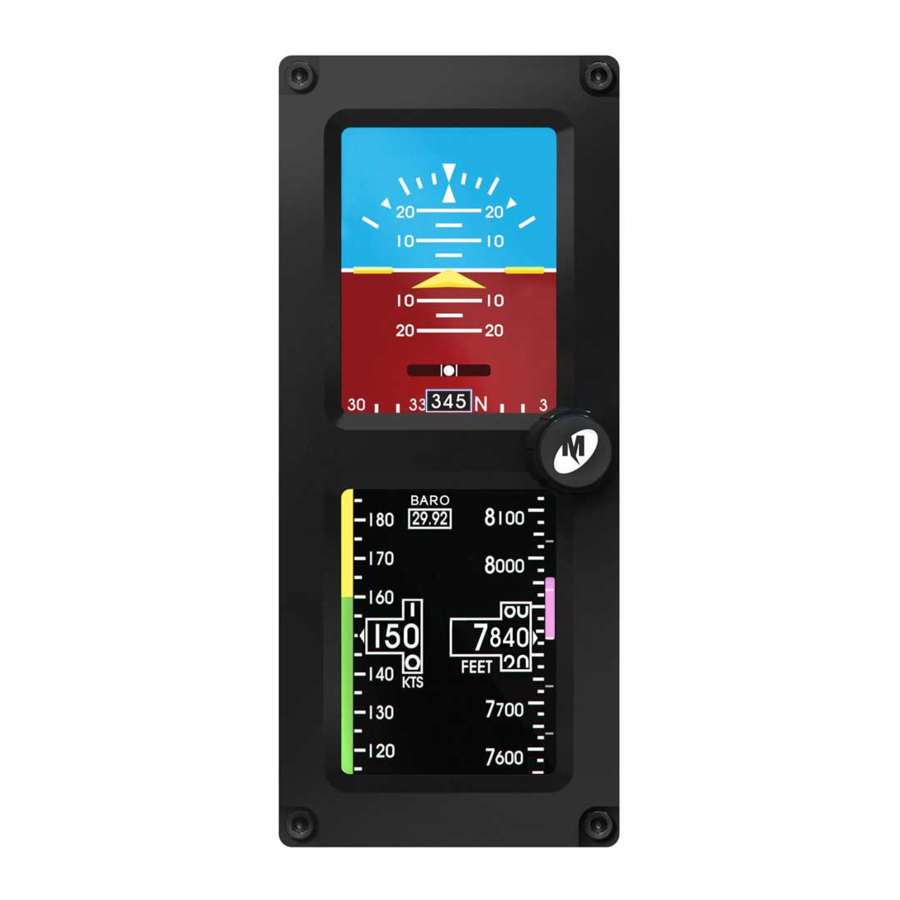
FLIGHT MODE Image 2 FLIGHT MODE HORIZONTAL ORIENTATION Image 3 In Flight Mode, the unit operates normally by displaying six functions: Attitude, Altitude, Airspeed, Slip, Vertical Trend, and Heading Information (Images 2, 3). FLIGHT MODE VERTICAL ORIENTATION REV. F Sept 15, 2015 Manual Number 9017846... -
Page 8: Attitude Operation
Flight Mode / ATTITUDE OPERATION The Attitude Indicator portion of the display (Image 4) will always appear on the top display when oriented vertically and can be configured to appear on the right or left display when oriented horizontally. The Attitude Indicator consists of seven parts: Horizon Line, Sky (blue), Ground (brown), Symbolic Airplane, Roll Scale, Pitch Scale and Slip Indicator. - Page 9 Flight Mode / ATTITUDE OPERATION The Pitch Scale is depicted as a series of graduations representing pitch angles every 5°, with every 10° graduation being wider and numbered. The unit is operable and usable in a continuous and unlimited pitch range of 360°+. ATTITUDE OPERATION Pitch Scale Roll/Bank Scale...
- Page 10 Flight Mode / ATTITUDE OPERATION A series of chevrons (^) will appear overlaid on the Pitch Scale at attitudes greater than ± 45°. This is to indicate to the pilot the direction of the horizon for quick reference when in an unusual pitch attitude (Image 5).
-
Page 11: Slip Operation
Flight Mode / SLIP OPERATION The Slip Indicator portion of the display will appear at the bottom of the Attitude Display (Image 5). If Heading Operation is enabled, the Slip Indicator will appear to the left and above the Heading Window in horizontal orientation, and directly above the Heading Window in vertical orientation (Image 6). -
Page 12: Heading Operation
Flight Mode / HEADING OPERATION Heading Operation can be configured during installation. The heading information is comprised of a window showing the current heading and a moving scale located along the bottom of the display (Image 6). The Heading Scale is depicted as a series of graduations every 10°... - Page 13 Flight Mode / HEADING OPERATION The Heading data is received directly from ARINC input and displayed without reprocessing. If ARINC input data is lost, the display will read “---” (Image 7). HEADING OPERATION ARINC data loss shown below. Image 7 ARINC DATA LOSS REV.
-
Page 14: Altitude Operation
Flight Mode / ALTITUDE OPERATION The Altimeter Indicator portion of the display will always appear on the bottom display when oriented vertically and can be configured to appear on the right or left display when oriented horizontally (Image 8). The Altimeter consists of four parts: Altitude Window, Altitude Scale, Barometric Setting Window and optional Altitude/Vertical Trend Bar. - Page 15 Flight Mode / ALTITUDE OPERATION ALTITUDE OPERATION Altitude display shown below. Altitude/Vertical Trend Bar Altitude Scale Barometric Setting Window Image 8 Altitude Altitude Units of Measure Window/Pointer REV. F Sept 15, 2015 Manual Number 9017846...
- Page 16 Flight Mode / ALTITUDE OPERATION or decreasing nature of the aircraft’s altitude. The Barometric Window shows the currently set barometric pressure. It is identified by the abbreviation BARO and is located at the top center of the Airspeed/Altitude Display. Setting the current barometric pressure compensates the altitude for the appropriate environmental conditions.
- Page 17 Flight Mode / ALTITUDE OPERATION Image 9 The Barometric Setting will turn green during adjustment. Image 10 Two arrows appear on either side of BARO when synronized. REV. F Sept 15, 2015 Manual Number 9017846...
-
Page 18: Airspeed Operation
Flight Mode / AIRSPEED OPERATION The Airspeed Indicator portion of the display will always appear on the bottom display when oriented vertically and can be configured to appear on the right or left display when oriented horizontally (Image 11). The Airspeed Indicator Display consists of three parts: Airspeed Window, Airspeed Scale and Airspeed Limitations or Range Markings. - Page 19 Flight Mode / AIRSPEED OPERATION AIRSPEED OPERATION Airspeed display shown below. Range Markings Airspeed Scale Image 11 Airspeed Airspeed Units Window/Pointer REV. F Sept 15, 2015 Manual Number 9017846...
- Page 20 Flight Mode / AIRSPEED OPERATION The Airspeed Limitations, also known as “V-speeds” or Range Marks, are indicated with colored range marking bands placed vertically along the left margin next to the Airspeed Scale. The colors and values of each bar can be set during installation in Configuration Mode by the installer only.
-
Page 21: Menu Operation
Flight Mode / MENU OPERATION Menu operation is simple and intuitive. Menu Title White text on a blue background at the top of each menu and sub-menu Current Item Selected Highlighted by a white box and green background Selectable Items Any selectable item on the menu is indicated in white text Submenu Items... -
Page 22: Options Menu
OPTIONS MENU While in Flight Mode, the Options Menu is available to the pilot or cockpit crew members. It offers multiple selections that are available during flight and do not affect the aircraft-specific configuration of the unit. Options are provided for convenience, preference, or potentially necessary in-flight adjustments (Image 12). -
Page 23: Alt Units
Options Menu / ALT UNITS The ALT Units setting allows the user to select the altitude unit of measure to either feet or meters. This feature is available during flight in the event that the aircraft crosses territorial airspace that requires or reports different altitude units (Image 13). -
Page 24: Baro Units
Options Menu / BARO UNITS The BARO Units setting allows the user to select the altitude baro- metric adjustment unit of measure to either inHg (inches of mercury) or MBAR (millibars). This feature is available during flight in the event that the aircraft crosses territorial airspace that requires or reports different barometric pressure units (Image 14). -
Page 25: Attitude Symbol
Options Menu / ATTITUDE SYMBOL The Symbol setting allows the user to select the type of symbolic airplane on the Attitude Display to either delta-wing or traditional. This feature is provided for pilot preference and to match other instruments in the panel (Images 15, 16, 17). Image 15 Image 16 Image 17... -
Page 26: Att Mask
Options Menu / ATT MASK The ATT Mask setting allows the user to turn the Attitude Mask ON or OFF. The Attitude Mask provides gradient dimming of the corners of the Attitude Display to give the aesthetic look of a round instrument (Images 18, 19, 20). -
Page 27: Alt Trend
Options Menu / ALT TREND The ALT Trend setting allows the user to turn the Altitude Trend Bar ON or OFF. The Altitude Trend Bar provides a graphical representation of vertical speed near the Altitude Scale (see Altitude Operation, page 10). -
Page 28: Info
Options Menu / INFO The INFO submenu is found within the Options Menu (Image 22). It offers multiple selections that are available during Flight Mode that do not affect the aircraft-specific configuration of the unit. The options available allow the user to access the Review Configuration (Review CFG) and Battery INFO screens (Image 23). -
Page 29: Review Configuration
Options Menu / INFO / REVIEW CONFIGURATION The Review CFG selection (Image 23) allows the user to review all of the values saved in unit memory previously set in Configuration Mode during installation or maintenance. There are no selectable options and this feature provides a view-only verification of information. When selected, the Review CFG screen will appear and allow the user to scroll through all of the configuration values (Image 24). -
Page 30: Battery Info
Options Menu / INFO / BATTERY INFO The Battery INFO selection allows the user to view the real-time status of the internal battery. The information available includes the Estimated Run Time in minutes, the Temperature in Celsius, the current battery State of Charge percentage, and the Battery Capacity in milliamp-hours (Image 25). -
Page 31: Exit Menu
Options Menu / EXIT MENU The Exit Menu action allows the user to manually exit the Options Menu and return to the active Attitude Display. There are no selectable options. After confirming any setting by selecting it, that setting will become active and it will be saved in memory. -
Page 32: Power Off
Options Menu / POWER OFF The Power OFF action allows the user to immediately turn the unit OFF when it is operating on its internal battery and there is no airspeed (<30 kts) detected. This item is typically grayed out and unavailable in Flight Mode. -
Page 33: Brightness Adjustment
Options Menu / BRIGHTNESS ADJUSTMENT SAM can be configured to adjust its brightness based on the aircraft’s manual lighting bus control or automatically, based on the ambient lighting conditions using the photocell sensor on the unit. For either option, the pilot or crew member can temporarily override the current brightness and manually increase or decrease brightness. -
Page 34: Emergency Operation
Emergency Operation / IN FLIGHT SAM is designed to operate reliably and provide the critical situational awareness needed, even if the aircraft power systems fail. Should this occur, the unit provides emergency operation by continuing to perform seamlessly and uninterrupted in the Flight Mode. SAM contains an internal and field-replaceable True Blue Power ®... -
Page 35: In Flight
Emergency Operation / IN FLIGHT Should the battery power become low while in operation, the battery icon will be displayed. This is identified by a black battery icon with a red X on it. This indicates that there is less than 20% of battery capacity left and may represent as little as ten minutes of backup power available (Image 30). -
Page 36: On The Ground
Emergency Operation / ON THE GROUND If primary aircraft power to the unit is lost, the unit will immediately begin operating on internal battery power. When this occurs, as a result of normal landing and shut-down procedure, the unit will recognize that there is minimal airspeed and determine that the aircraft is on the ground. -
Page 37: Alerts And Annunciations
ALERTS AND ANNUNCIATIONS A brief summary of the unit’s dynamic limits are presented within this section. If these limits are exceeded in flight, or should an error occur that produces misleading information, the data in question will be replaced with a red X (Images 32, 33, 34). A more complete list of limitations can be found in the Specifications section of this Guide (see Product Specifications, page 39). - Page 38 ALERTS AND ANNUNCIATIONS Image 33 The airspeed instrument is absent, possibly due to exceedance of the pressure sensor range. This may self-correct, but if the red X persists, the unit should be serviced immediately. Image 34 The altimeter instrument is absent, possibly due to exceedance of the pressure sensor range.
-
Page 39: Service Reminder
SERVICE REMINDER The service actions listed in this section represent partial Instructions for Continued Airworthiness (ICA) which are recommended or required by the FAA and/or the manufacturer. Pressure System and Altimeter Verification Per Federal Regulation 14 CFR 91.411, it is required that each static pressure system and each altimeter have been tested and inspected within the last twenty-four (24) months. - Page 40 SERVICE REMINDER Software Updates Mid-Continent will have, on occasion, the need to update software versions on SAM for maintenance, improvements or the addition of functionality. With the unit’s easy, field-upgrade option, it does not have to be returned to the factory for software updates. In some cases, the unit may not have to be removed from the panel.
- Page 41 SERVICE REMINDER Battery Replacement Regularly scheduled maintenance of the True Blue Power lithium ® iron phosphate battery is not required. The battery module is rated for an estimated life of six (6) years. Extreme temperature, repeated full-depth discharges or other abuse may reduce battery life. A battery capacity check occurs each time the unit is powered on.
- Page 42 SERVICE REMINDER Disposal Dispose of lithium-ion batteries in accordance with local, state and federal laws and regulations. Lithium-ion batteries do contain recyclable material. For recycle information, call (877) 273-2925 or visit www.call2recycle.org. Care and Cleaning The bezel of the unit is made of black anodized aircraft-grade aluminum.
-
Page 43: Product Specifications
PRODUCT SPECIFICATIONS Power Input 10-32 VDC; 6W nominal, 25W max Output ARINC 429 (high or low speed, see manual for specific labels) Operating Range Attitude 300° per second pitch, roll and yaw (max) Altitude -1,500 to +55,000 ft (-457 m to 16,764 m) Airspeed 20 to 500 knots (23 to 575 mph) (37 to 926 kph) Heading... -
Page 44: Limited Warranty
LIMITED WARRANTY Mid-Continent Instruments and Avionics understands customer satisfaction is the cornerstone of our business. If you are dissatisfied for any reason, let us know. For assistance, contact a customer service representative at either of our two locations. We provide a limited warranty for all new SAM — MD302 Standby Attitude Modules for two (2) years after date of original sale. -
Page 45: Product Registration
PRODUCT REGISTRATION To register your unit, return the enclosed product registration card to: Mid-Continent Instruments and Avionics Attn: Product Support 9400 East 34th Street North Wichita, Kansas 67226 USA You may also visit flySAM.com/registration to enter the requested information online. REV. - Page 46 NOTES REV. F Sept 15, 2015 Manual Number 9017846...
- Page 47 Compact. Flexible. Advanced. 2-inch attitude, altitude, airspeed and slip. ® The MD302 Standby Attitude Module — SAM — is the first digital standby to provide attitude, altitude, airspeed, slip, vertical trend, and heading information in an advanced, 2-inch format. SAM delivers an easy-to-fit, compact design with selectable orientation (horizontal and vertical) like no other, ensuring a perfect fit within any panel.
- Page 48 Kansas California 9400 East 34th Street North 16320 Stagg Street Wichita, Kansas 67226 USA Van Nuys, California 91406 USA 316.630.0101 800.821.1212 818.786.0300 800.345.7599 Fax 316.630.0723 Fax 818.786.2734 mci@mcico.com mcw@mcico.com flySAM.com Copyright © 2015 Mid-Continent Instrument Co., Inc.
Need help?
Do you have a question about the SAM MD302 and is the answer not in the manual?
Questions and answers