
Summary of Contents for YTL YTL-007-155
- Page 1 CHIPPER SHREDDER WITH METAL HOPPER OPERATING INSTRUCTIONS Read this manual before using this product. Failure to do so may result in serious injury. SAVE THIS MANUAL REV042619 CR6502...
-
Page 2: Table Of Contents
Table of Contents General Warnings ....................3 Specific Safety Rules and Precautions ..............4 Controls and Features Identification ..............6 Assembly Instructions ..................7 Operation Instructions ..................10 Inspection, Maintenance and Cleaning .............. 11 Specifications ..................... 12 Parts Drawings & Parts List ................13 Limited Warranty .................... -
Page 3: General Warnings
General Warnings Please Read All Instructions Before Operation 1. Keep your work area clean and use bright lighting. Cluttered benches and dark areas invite accidents. 2. Do not operate the chipper/shredder in flammable and/or explosive environments, such as in the presence of flammable liquids, gases, or dust. -
Page 4: Specific Safety Rules And Precautions
2. Check and maintain labels and nameplates on the chipper/shredder as the contain important information. If a label or nameplate is unreadable or missing, please contact YTL International for a replacement. 3. Make sure to operate the chipper/shredder only on a flat, level, sturdy surface capable of supporting the weight of the chipper/shredder and any additional tools and equipment. - Page 5 FIRE AND EXPLOSION PRECAUTIONS Gasoline fuel and fumes are flammable and potentially explosive. Always properly store and handle fuel. It’s recommended to keep multiple ABC class fire extinguishers nearby when operating the unit. Always keep the chipper/shredder, its’ engine, and all surrounding work areas clean. Be diligent in checking carefully for potentially flammable materials around the unit prior to operation.
-
Page 6: Controls And Features Identification
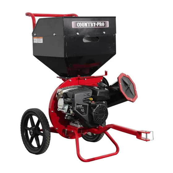
Controls and Features Identification 1. Handle: Easy Maneuverability 2. Shredder Hopper: 1/2” Max. Limb Diameter 3. Discharge Port: Cover Cap/End 4. Wheels: 14” flat free tires 5. Chipper Chute: 3’’Maximum Diameter 6. Support Leg: Stabilizes the Engine During Operation 7. Engine: 6.5HP 8. -
Page 7: Assembly Instructions
Assembly Instructions STEP 1: Attach Support Leg 1. Attach support leg to the engine mounting plate using two sets of hex bolt M8x40 and nylon lock nut M8. Then lock with two safety pins. STEP 2: Attach Wheel 1. Attach wheel to the wheel axle using two flat washers Ø12 and cotter pin Ø3x30. - Page 8 STEP 3: Attach Handle 1. Attach the handle to the hopper using four sets of hex bolt M8x20 and nylon lock nut M8. STEP 4: Attach Hopper Fence 1. Attach hopper fence to the hopper using six sets of hex bolt M8x16 and nylon lock nut M8.
- Page 9 STEP 5: Attach Tow Bar 1. Attach tow bar to the engine mounting plate using safety pin. STEP 6: Attach Bag Support Rod 1. Attach bag support rod into the bag rack, then stick the flat part into the slot.
-
Page 10: Operation Instructions
Operating Instructions Before Starting Always use safety equipment. Remember to wear ANSI approved safety impact goggles, hearing protection, heavy duty work gloves, and a dust mask or respirator when using this product. Check underneath the chipper/shredder to look for oil and/or liquid spots indicating an oil or gas leak. If there are any leaks, do not use the chipper/shredder and contact a qualified repair professional for maintenance. -
Page 11: Inspection, Maintenance And Cleaning
with a long stick. Only when the jam is cleared from the machine is it safe to resume operation. When finished using the chipper/shredder, turn the engine’s On/Off switch to its “OFF” position. Wait until the machine completely stops before moving or cleaning the chipper/shredder. Store the unit (with spark plug removed) in a clean, dry, safe location out of reach of children and unauthorized people. -
Page 12: Specifications
Specifications Chipper Chute Capacity……………………………………3’’ Maximum Diameter Chipper Chute Dimension…………………….………..11.57” x 8” Oval opening Shredder Hopper Capacity ……………………….1/2” Maximum Limb Diameter Shredder Hoppe Dimension…………………………...………19.6” L x 15.77” W Accessories…………………….Protective Glasses, Earmuff, Discharge Bag Wheel Type…………………………………………………………14” flat free tires Engine Type…………………………………………….……………………..6.5HP Overall Size……………………………………………..……24’’ X42.78’’ X41.56’’ Packaging Size……………………………………………….25.6”x21.57”x48.82”... -
Page 13: Parts Drawings & Parts List
Parts Drawing & Parts List... - Page 14 Parts Drawing & Parts List ITEM Drawing No DESCRIPTION 9115-06016 Hex Flange Bolt M6x16 CP6502-00007 Batten CP6502-00006 Shredder Hopper Protective Film CP6502-01000 Shredder Hopper CP6502-00001 Handle CP6502-00002 14” Flat Free Tire 9301-12000 Flat Washer Ø12 9404-03030 Cotter Pin Ø3x30 9206-06000 Nylon Lock Nut M6 CP6502-02000 Rotor Housing...
- Page 15 CP6502-09004 Chipper Chute Mounting Ring CP75-00007 Engine Mounting Block CP6502-00004 Support Leg 9101-08040 Hex Bolt M8x40 T680-20000 Lock Pin CP6502-10000 Engine Mounting Plate 9301-08000 Flat Washer Ø8 CP6502-07000 Tow Bar 9901-06016 Hex Bolt M6x16 HR265-3112 Engine CP6502-00008 Cover 9901-08030-8.8 Hex Bolt M8x30 CP6502-08000 Wind Deflector 9404-4*90...
-
Page 16: Limited Warranty
Limited Warranty Warranty For one year from the date of purchase YTL International will replace for the original purchaser. The warranty will not apply to any unit which was not assembled correctly, misused, overloaded or which has been used or operated contrary to our instructions, or which has been repaired or altered by anyone other than an authorized representative.
Need help?
Do you have a question about the YTL-007-155 and is the answer not in the manual?
Questions and answers
where is the on switch?
The On switch for the YTL-007-155 chipper/shredder is located on the engine.
This answer is automatically generated
Blades for model Tyler 007 155