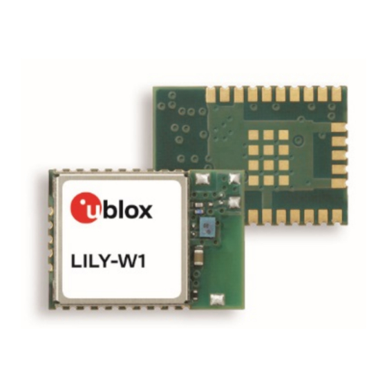
u-blox LILY-W1 Series System Integration Manual

u-blox LILY-W1 Series System Integration Manual

Host-based
Table of Contents

Advertisement

Quick Links

LILY-W1 series
Host-based Wi-Fi modules
System integration manual
Abstract
This document describes LILY-W1 series short range Wi-Fi front end modules. These host-based
modules are ultra-compact cost efficient IEEE 802.11b/g/n Wi-Fi front end modules in the LILY form
factor. This module series includes variants with or without internal antenna and LTE filter. It
includes an integrated MAC/Baseband processor and RF front end components. It can connect to a
host through its SDIO or USB interface.
www.u-blox.com
UBX-15027600 - R09

Advertisement

Table of Contents
loading

Summary of Contents for u-blox LILY-W1 Series

  • Page 1 System integration manual Abstract This document describes LILY-W1 series short range Wi-Fi front end modules. These host-based modules are ultra-compact cost efficient IEEE 802.11b/g/n Wi-Fi front end modules in the LILY form factor. This module series includes variants with or without internal antenna and LTE filter. It includes an integrated MAC/Baseband processor and RF front end components.
  • Page 2: Document Information

    The information contained herein is provided “as is” and u-blox assumes no liability for its use. No warranty, either express or implied, is given, including but not limited to, with respect to the accuracy, correctness, reliability and fitness for a particular purpose of the information.
  • Page 3: Table Of Contents

    LILY-W1 series - System integration manual Contents Document information ..........................2 Contents ................................3 System description ..........................6 1.1 Overview and applications ........................6 1.1.1 Module architecture ........................... 7 1.1.2 Radio interface ............................ 7 1.1.3 Operation modes ..........................7 1.2 Pin configuration and function ......................... 8 1.2.1 Pin attributes ............................
  • Page 4 LILY-W1 series - System integration manual 2.6.3 Layout and manufacturing ......................26 2.7 Module footprint and paste mask ......................26 2.8 Thermal guidelines ...........................27 2.9 ESD guidelines ............................28 2.10 Design-in checklist ............................29 2.10.1 Schematic checklist .........................29 2.10.2 Layout checklist ..........................29 Software ..............................30 3.1 Driver versions ............................30...
  • Page 5 Regulatory compliance ........................46 5.1 General requirements ..........................46 5.2 FCC/IC End-product regulatory compliance ..................46 5.2.1 Referring to the u-blox FCC/IC certification ID ................47 5.2.2 Obtaining own FCC/IC certification ID ..................47 5.2.3 Antenna requirements ........................48 5.2.4 Software configuration and control ....................48 5.2.5 Operating frequencies ........................48...
  • Page 6: System Description

    System description 1.1 Overview and applications The LILY-W1 series modules are ultra-compact Wi-Fi front end modules that include variants with or without an internal antenna and LTE filter to enable in-device co-existence without jeopardizing Wi- Fi performance. They are designed for integration with an LTE radio application. LILY-W1 supports IEEE 802.11b/g/n standards.
  • Page 7: Module Architecture

    Home automation and appliances • Transport and logistics devices 1.1.1 Module architecture The block diagram of the LILY-W1 series module is provided in this section and is valid for both variants. Figure 1: LILY-W1 block diagram 1.1.2 Radio interface The LILY-W1 series modules support Wi-Fi 802.11b/g/n operation in the 2.4 GHz radio band and are available in the following two variants: •...
  • Page 8: Pin Configuration And Function

    AP Beaconing Active Tx/Rx data connection enabled and system runs at specified power consumption. Table 2: Description of operation modes for LILY-W1 series 1.2 Pin configuration and function 1.2.1 Pin attributes The pin attributes described in Table 3 are: 1.
  • Page 9: Pin List

    LILY-W1 series - System integration manual 1.2.2 Pin list Figure 2 and Table 3 list the pin-out of the LILY-W1 module, with pins grouped by function. Figure 2: LILY-W1 pin assignment (top view) Function Pin Name Pin No. Power Type...
  • Page 10: Supply Interfaces

    1.3 Supply interfaces 1.3.1 Main supply inputs The power for the LILY-W1 series modules must be supplied via the VCC and VCC_IO pin. All supply voltages used inside the modules are generated from the VCC through internal LDOs. The current drawn by the LILY-W1 series through the VCC pins can vary by several orders of magnitude depending on operation mode and state.
  • Page 11: Power-Up Sequence

    During power up of the LILY-W1 series module, it is a good practice to enable VCC first, followed by VCC_IO shortly after to reduce the inrush current from the main supply. It is suggested that the PD- n is held low during start up and be released when the power is stable or later, when the module must be turned on.
  • Page 12: Module Power-Off

    Table 5: Wake-up signal definition 1.4.4 Configuration signals LILY-W1 series module uses the USB/SDIO-n pin as host interface configuration input to set the desired operation mode following a Power on sequence. Strap configuration options are listed in Table USB/SDIO-n signal is powered by the internal 1.8 V voltage domain and is used to determine communication busses configuration and host-side drivers.
  • Page 13: Usb 2.0 Interface

    LILY-W1 series - System integration manual • Allows card to interrupt host Table 7 summarizes the bus speed modes supported by the module. Bus Speed Mode Max. Bus Speed [MB/s] Max. Clock Frequency [MHz] High Speed Default Speed 12.5 Table 7: SDIO supported rates Pull-up resistors are required for all SDIO data and command lines.
  • Page 14: Antenna Interfaces

    The following recommendations apply while developing an antenna interface for the LILY-W1 module: • Where possible, consider integrating in the end product the u-blox reference design to minimize the effort on the certification process. See Appendix B for the full list of available reference designs.
  • Page 15: Design-In

    Design-in 2.1 Overview For an optimal integration of LILY-W1 series modules in the final application board, it is recommended to follow the design guidelines stated in this chapter. Every application circuit must be properly designed to guarantee the correct functionality of the related interface, however a number of points require high attention during the design of the application device.
  • Page 16: Rf Transmission Line Design (Lily-W131 Only)

    LILY-W1 series - System integration manual Therefore, module integrators must either follow exactly one of the antenna reference design used in the module’s FCC type approval and detailed in Annex B or certify their own designs. 2.2.1 RF transmission line design (LILY-W131 only) RF transmission lines such as the one from the ANT pin up to the related antenna connectors must be designed so that the characteristic impedance is as close as possible to 50 Ω.
  • Page 17: Antenna Design (Lily-W131 Only)

    LILY-W1 series - System integration manual FR-4 material exhibits poor thickness stability and thus less control of impedance over the trace length. Contact the PCB manufacturer for specific tolerance of controlled impedance traces. • For PCBs using components bigger than 0402 and dielectric thickness below 200 µm, it is recommended to add a keep-out (that is, clearance, a void area) on the ground reference layer below any pin present on the RF transmission lines to reduce parasitic capacitance to ground.
  • Page 18 LILY-W1 series - System integration manual minimum frequency that has to be radiated, given that the orientation of the ground plane related to the antenna element must be considered. The RF isolation between antennas in the system has to be as high as possible and the correlation between the 3D radiation patterns of the two antennas has to be as low as possible.
  • Page 19 LILY-W1 series - System integration manual Isolation > 15 dB recommended The antenna to antenna isolation is the S parameter between the two antennas in the band of operation. (in-band) > 10 dB acceptable Isolation Out-of-band isolation is evaluated in the band of the >...
  • Page 20 LILY-W1 series - System integration manual ☞ A de-facto standard for SMA connectors implies the usage of reverse polarity connectors (RP- SMA) on end-user accessible Wi-Fi interfaces to increase the difficulty to replace the antenna with higher gain versions and exceed regulatory limits.
  • Page 21: On-Board Antenna Design (Lily-W132 Only)

    LILY-W1 series - System integration manual B8343 B39242B8343P810 Requires external matching network (two inductors) B9604 B39242B9604P810 Requires external matching network (one inductor) TriQuint 885071 885071 Requires external matching network (two inductors) TriQuint 885032 885032 Avago ACPF-7424 ACPF-7424 No external matching required Taiyo Yuden FBAR dev.
  • Page 22: Supply Interfaces

    VCC and VCC_IO pins with proper DC power supplies that comply with the requirements summarized in Table 4. Good connection of the LILY-W1 series module power supply pins with DC supply source is required for accurate RF performance and schematic guidelines are summarized below: •...
  • Page 23 LILY-W1 series - System integration manual Additional bypass capacitors in the range of 100 nF to 1 µF on all supply pins are required for high • frequency filtering. The preferred choice is a ceramic capacitor with X7R or X5R dielectric due to low ESR/ESL.
  • Page 24: Data Communication Interfaces

    Table 15: SDIO bus requirements 2.4.2 USB 2.0 The USB bus of LILY-W1 series supports Hi-Speed connectivity with a transfer rate of 480 Mb/s. USB differential data pair is a controlled impedance bus and the main parameters considered for the track impedance calculation are depicted in Figure 9.
  • Page 25: Other Interfaces And Notes

    LILY-W1 series - System integration manual Figure 9: USB differential pair, controlled impedance parameters The USB data lines must follow the recommendations stated in Table 16 to guarantee bus signal integrity and avoid EMI issues. Signal Group Parameter Min. Typ.
  • Page 26: Component Placement

    PCB. 2.7 Module footprint and paste mask Figure 10 describes the pin layout for the LILY-W1 series module. The proposed land pattern layout reflects the pin layout of the module. Both Solder Mask Defined (SMD) and Non Solder Mask Defined...
  • Page 27: Thermal Guidelines

    2.8 Thermal guidelines The LILY-W1 series modules have been successfully tested from -40 °C to +85 °C ambient temperature. The board will generate heat during high loads that must be dissipated to sustain the lifetime of the components.
  • Page 28: Esd Guidelines

    LILY-W1 series - System integration manual • Minimum board size: 25x35 mm • Power planes and signal traces should not cross the layers beneath the module to maximize heat flow from the module. Additional hardware techniques can be used to improve the thermal performance of the module in customer’s applications:...
  • Page 29: Design-In Checklist

    2.10.2 Layout checklist  PCB stack-up and controlled impedance traces follow PCB manufacturer’s recommendation.  All pins are properly connected and the package follows u-blox’s recommendations for pin design.  Proper clearance has been provided between RF section and digital section.
  • Page 30: Software

    SDIO 2.0 or USB 2.0 device interface. From the software point of view, the LILY-W1 series modules contain only calibration data and basic operation settings in an on-board non-volatile memory and thus require a host-side driver and a firmware to run.
  • Page 31: Driver And Firmware Architecture

    LILY-W1 series - System integration manual 3.3 Driver and firmware architecture The software for the LILY-W1 modules is split into the following parts: • The Wi-Fi driver, running on the host system • The device firmware, which runs on the module itself The host drivers interface with the SDIO or USB bus drivers and upper layer protocol stacks of the Linux/Android system.
  • Page 32: Compiling The Drivers

    [4]. 3.4.1.2 Kernel configuration According to the used host interface, the drivers for the LILY-W1 series modules depend on the MMC/SDIO or the USB stack of the Linux kernel; thus the respective stack must be enabled on the target system.
  • Page 33: Compile-Time Configuration

    LILY-W1 series - System integration manual Once you remove the archives, you should find something similar to the following in your working directory: ├── FwImage/ │ └── sd8801_uapsta.bin # SDIO firmware image (USB version: usb8801_uapsta.bin) └── SD-8801-FC18-MMC-14.85.36.p101-C3X14160_B0-GPL/ └── wlan_src/ # Wi-Fi driver and tools sources ├──...
  • Page 34: Deploying The Software

    LILY-W1 series - System integration manual This command will build the Wi-Fi kernel modules and all the included user space applications. The build results will be copied to ../bin_sd8801/ (or ../bin_usb8801 in case of USB driver), relative to the wlan_src directory. The following table summarizes the content of the Wi-Fi build results directory:...
  • Page 35: Additional Software Requirements

    LILY-W1 series - System integration manual blacklist mwifiex blacklist mwifiex_sdio Listing 3: Blacklisting mwifiex ⚠ Blacklisting will not work for drivers that are built into the kernel image rather than as a kernel module. 3.5.2 Additional software requirements Some additional packages that are recommended for installation on the target system are mentioned...
  • Page 36: Usb Driver

    LILY-W1 series - System integration manual wlan: Loading MWLAN driver wlan: Driver loaded successfully mmc1: new high speed SDIO card at address 0001 vendor=0x02DF device=0x9139 class=0 function=1 rx_work=0 cpu_num=1 Request firmware: mrvl/sd8801_uapsta_sdio.bin Wlan: FW download over, firmwarelen=234524 downloaded 234524 WLAN FW is active fw_cap_info=0xba3, dev_cap_mask=0xffffffff wlan: version = SD8801-14.85.36.p101-C3X14C160-GPL-(FP85)
  • Page 37: Unloading The Drivers

    LILY-W1 series - System integration manual wlan: Loading MWLAN driver usbcore: registered new interface driver usb8xxx wlan: Driver loaded successfully usb 2-1: new high-speed USB device number 4 using musb-hdrc […] Request firmware: mrvl/usb8801_uapsta_usb.bin WLAN FW is downloaded usb_reset_device() successful.
  • Page 38: Prevent High Current In Deep Sleep

    HWaddr 02:50:43:20:12:36 3.8 Prevent high current in deep sleep Due to internal configuration settings of the used chipset, the LILY-W1 series modules have an unintended high current consumption after firmware download. The current consumption for the deep sleep mode in that case is above 1.4 mA. To prevent the high current consumption, execute the...
  • Page 39: Applying The Transmit Power Limit Configuration

    LILY-W1 series - System integration manual ChanTRPC.TlvType:2=0x0189 ChanTRPC.TlvLength:2={ TLVStartFreq:2=2407 TLVChanWidth:1=20 TLVChanNum:1=1 TLVPwr:20='0,16,1,14,2,14,3,14,4,13,5,13,6,13,7,13,8,13,9,13' Listing 6: Example transmit power limit configuration for channel 1 The format for the parameters is described in Table 23. Field name Type Description TLVStartFreq UINT16 Starting frequency of the band for this channel: 2407, 2414 or 2400 for 2.4 GHz...
  • Page 40: Adaptivity Configuration (Energy Detection)

    LILY-W1 series - System integration manual 3.10 Adaptivity configuration (Energy Detection) The LILY-W1 series modules support the adaptivity requirements (energy detection) as per the EN 300 328 standard for Wi-Fi. The adaptivity or Energy Detect mechanism must be explicitly enabled after the startup of the module, and correct detection threshold values must be configured.
  • Page 41: Wi-Fi Station Mode

    LILY-W1 series - System integration manual ☞ -ddd Adding to this command generates debug logs. This command option is useful for debugging any issues related to the bring-up with access point. To assign an IP address to the access point interface: ifconfig uap0 192.168.1.1...
  • Page 42: Compile-Time Debug Options

    LILY-W1 series - System integration manual 3.12.1 Compile-time debug options The extent to which debug messages are available for printing at runtime is controlled by the CONFIG_DEBUG variable in the driver's Makefile. The CONFIG_DEBUG variable can have the following values: •...
  • Page 43: Handling And Soldering

    The bow and twist of the PCB is maximum 0.75% according to IPC-A-610E. The thickness of solder resist between the host PCB top side and the LILY-W1 series module bottom side must be considered for the soldering process.
  • Page 44: Cleaning

    LILY-W1 series - System integration manual The module is compatible with industrial reflow profile for RoHS solders. Use of "No Clean" soldering paste is strongly recommended. The reflow profile used is dependent on the thermal mass of the entire populated PCB, heat transfer efficiency of the oven and particular type of solder paste used.
  • Page 45: Other Notes

    LILY-W1 series - System integration manual • Cleaning with water will lead to capillary effects where water is absorbed in the gap between the baseboard and the module. The combination of residues of soldering flux and encapsulated water leads to short circuits or resistor-like interconnections between neighboring pins. Water will also damage the sticker and the ink-jet printed text.
  • Page 46: Regulatory Compliance

    , CE mark, National Communications Commission (NCC), and the Japanese Ministry of Information and Communication (MIC). This chapter contains instructions on the process of integrating LILY-W1 series modules into an end- product. • Any deviation from the process described may cause the LILY-W1 series module not to comply with the regulatory authorizations of the module and thus void the user's authority to operate the equipment.
  • Page 47: Referring To The U-Blox Fcc/Ic Certification Id

    See also section 5.2.3. ⚠ To use the u-blox FCC / ISED grant and refer to the u-blox FCC ID / ISED certification ID, the integrator must confirm to u-blox that the software configuration and control requirements as described in section 5.2.4 are fulfilled.
  • Page 48: Antenna Requirements

    Class II Permissive Change. ⚠ Integrators that intend to refer to the u-blox FCC ID / ISED certification ID must contact their local support team to discuss the Permissive Change Process. For contact information, see Contact. Note also that Class II Permissive Changes are subject to additional NRE costs.
  • Page 49: End Product Labeling Requirements

    12 – 13 2467 – 2472 Table 25: Allowed channel usage under FCC/ISED regulation 5.2.6 End product labeling requirements For an end-product using the LILY-W1 series, there must be a label containing, at least, the following information: This device contains...
  • Page 50: Original Fcc And Ic Grant

    FCC/ISED ID and/or this statement, the FCC/ISED ID and the statement shall also be included in the end-product manual. 5.2.7 Original FCC and ISED grant LILY-W1 The original grant and the FCC/ISED IDs of the LILY-W1 series module can be found in the series Data Sheet [1] 5.3 CE End-product regulatory compliance 5.3.1 Safety standard In order to fulfill the safety standard EN 60950-1 [11], the LILY-W1 series module must be supplied with a Class-2 Limited Power Source.
  • Page 51: Modular Transmitter Requirements

    The end product is required either to integrate one of the antennas, which is approved with the module for use in Taiwan (see the LILY-W1 series Data sheet [1]), or apply for a Class II permissive change. 5.4.2 End product labeling requirements...
  • Page 52 Figure 13: Giteki mark, R , LILY-W1 MIC certification number. The recommended size of the Giteki mark is Ø5.0 mm, the minimum size allowed is Ø3.0 mm. Table 28 shows the channel restrictions while operating the LILY-W1 series in Wi-Fi mode in Japan: Channel...
  • Page 53: Product Testing

    Figure 14: Automatic test equipment for module test 6.2 OEM manufacturer production test As the testing is already done by u-blox, an OEM manufacturer does not need to repeat firmware tests or measurements of the module RF performance or tests over analog and digital interfaces in their production test.
  • Page 54: Go/No Go" Tests For Integrated Devices

    A basic RF functional test of the device including the antenna can be performed with standard Wi-Fi and Bluetooth devices as remote stations. The device containing the LILY-W1 series module and the antennas should be arranged in a fixed position inside an RF shield box to prevent interferences from other possible radio devices, in order to get stable test results.
  • Page 55 The module can also be set into TX test modes without using the utility. Sample scripts for this can be provided through u-blox support. The test modes for Wi-Fi still require the use of the manufacturing firmware. ⚠ To avoid module damage during transmitter test, a proper antenna according to module specifications or a 50 Ω...
  • Page 56: Appendix

    LILY-W1 series - System integration manual Appendix A Glossary Abbreviation Definition Advanced encryption standard Access point Application programming interface CCMP Counter with CBC-MAC protocol CMAC Cipher-based message authentication code Direct current DHCP Dynamic host configuration interface DTIM Delivery traffic indication message...
  • Page 57 LILY-W1 series - System integration manual Abbreviation Definition Wi-Fi Direct WLAN Wireless local area network Wi-Fi Protected Access Table 29: Explanation of the abbreviations and terms used UBX-15027600 - R09 Appendix Page 57 of 64 C1 - Public...
  • Page 58: B Antenna Reference Designs

    PCB layout must be identical to the one provided by u-blox, please implement one of the reference designs included in this annex or contact u-blox. • The designer must use the stack-up provided by u-blox. RF traces on the main PCB are part of the certified design. The available designs are presented in this annexure.
  • Page 59: Floor Plan And Pcb Stack-Up

    LILY-W1 series - System integration manual B.1.1 Floor plan and PCB stack-up This section describes where the critical components are positioned on the reference design. It also presents the stack-up of the four layers of the PCB. Figure 18: LILY-W131 antenna reference design...
  • Page 60: Rf Trace Specification

    LILY-W1 series - System integration manual B.1.3 RF trace specification The 50 Ω coplanar micro-strip dimensions used in these reference designs are stated in Figure 19 and Table 33. Figure 19: Coplanar micro-strip dimension specification Item Value 300 µm 540 µm 35 µm...
  • Page 61: C Wi-Fi Tx Output Power Limits

    LILY-W1 series - System integration manual C Wi-Fi Tx output power limits The maximum allowed conducted output power is limited depending on the regulatory domain / region the module is used. The antenna gain has to be added for EIRP figures.
  • Page 62: Related Documents

    [14] AS/NZS 4268: 2012 – Radio equipment and systems – Short range devices – Limits and methods of measurement. ☞ For regular updates to u-blox documentation and to receive product change notifications, register on our homepage (www.u-blox.com). UBX-15027600 - R09...
  • Page 63: Revision History

    LILY-W1 series - System integration manual Revision history Revision Date Name Comments sbia, mzes, 08-Mar-2016 Initial release. kgom sbia, mzes, 19-Apr-2016 Document status changed to Advance Information. kgom Updated Table 4 with measured values. Section 1 now clarifies the approach for FCC/ISEDC certification.
  • Page 64: Contact

    LILY-W1 series - System integration manual Contact For complete contact information, visit us at www.u-blox.com. u-blox Offices North, Central and South America Headquarters Asia, Australia, Pacific Europe, Middle East, Africa u-blox America, Inc. u-blox Singapore Pte. Ltd. u-blox AG Phone:...

This manual is also suitable for:

Lily-w131Lily-w132Lily-w131-00b

Table of Contents