Table of Contents
Advertisement
Quick Links
Advertisement
Table of Contents

Summary of Contents for Jergens ASG HIOS BLG BC2
- Page 1 Page | 1 HIOS BLG BC2 Programming Instructions Dec 2015...
-
Page 2: Table Of Contents
Thank you for buying an ASG BLG Series Tool. We know you have a choice in torque tools and we appreciate that you chose ASG. CONTENTS Page | 2 Subject Page User Interface Display and Button Functions Screw Count and Value Setting Display Section ... -
Page 3: User Interface Display And Button Functions
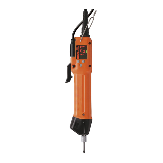
BC2 Programming Instructions BC2 tools feature a built in Screw Counter and a Pulse System. The Pulse System is a mechanism using an electronic signal (Pulse) that occurs during motor revolutions. By installing several fasteners into the assembly the driver learns the number of motor Page | 3 revolutions required to correctly tighten the fasteners to the desired torque. -
Page 4: F1 Button
User Interface Display and Button Functions Cont. 3. F1 Button Press and hold the F1 button until [ “P”] shows on the display. When the button is released [ON]* will show on the display. Page | 4 Continue to press F1 to scroll through the various set up functions. ... - Page 5 Quick Start Procedure Continued 2. Start learning the joint by driving 3 or more of the same fastener into the same joint. Make sure to use the same fasteners, parts and method of pick up to be used in production. As you drive each fastener you will see the actual number of motor Page | 5 revolutions displayed.
-
Page 6: Navigating The User Interface
Quick Start Procedure Continued The count, or batch, can be set between 1and 99, press the F2 button to move from the ones place to the tens place, press the F3 button again to increase the tens place between 0 and 9. Page | 6 When finished setting the count, save and exit by pressing and holding the F1 button until you hear the buzzer* sound twice and the word HIOS scrolls across the display. -
Page 7: Setting The Functions
Navigating the User Interface Continued ├ 4. With [ 1.0] showing, press and release F1 to see [ r 0.4] on the display. With [ r 0.4] showing, press and release F1 to see [ d03] on the display. Page | 7 5. -
Page 8: Setting The Minimum Revolutions
Setting the Functions Continued 3. Setting the Minimum Revolutions. (see screen #4 on page 6) Note! the BC2 counts Get to screen #4 with [u60] the motor revolutions, not the actual revolutions of the fastener! showing with the 0 flashing on the display by following the instructions for navigating on Page | 8 page 6. -
Page 9: Setting The Buzzer
Setting the Functions Continued 7. Setting the Buzzer. (see screen #8 on page 7) Get to screen #8 with [d03] showing with the 3 flashing on the display by following the instructions on pages 6&7. The buzzer can be set as an indicator, an alarm or to enable or disable various Page | 9 functions. -
Page 10: Adjust The Re-Hit Timer
Setting the Functions Continued 10. Adjust Re-Hit Timer. (see screen #11 on page 7) Get to screen #11 with [≡0.5] showing with the 5 flashing on the display by following the instructions on pages 6&7. The Re-Hit Timer sets a time period between the clutch shut off and a second or third Page | 10 trigger-pull-clutch-shut-off sequence before an Error / Fail is registered. -
Page 11: Minimum/Maximum Revolutions
General Information Continued Minimum/Maximum Revolutions. Remember that the Minimum and Maximum revolutions are the motor revolutions, not the number of revolutions of the bit, or fastener. You may notice a difference in the Maximum revolution numbers when driving Page | 11 fasteners of the same length. -
Page 12: Optional Equipment
Optional Equipment The BLG BC2 tools perform the counting and Error Proofing functions as standalone units. With the options below it is possible to add I/O capability, data capturing capability and the ability for process control by interfacing with a PLC or other controls. Page | 12 #65665 BLG BC2 I/O Cable with sample software.
Need help?
Do you have a question about the ASG HIOS BLG BC2 and is the answer not in the manual?
Questions and answers