
Related Manuals for Kleinn Air Horns SDKIT17-230STD

Summary of Contents for Kleinn Air Horns SDKIT17-230STD
- Page 1 SDKIT17-230/734STD INSTALLATION MANUAL REV: BETA (4/13/2020) © Kleinn Air Horns 2020, All rights reserved. PO Box 91278 Tucson, AZ 85752 Phone: (520) 579-1531 Web: www.Kleinn.com...
- Page 2 SDKIT17-230/734STD Installation and Operation Manual This digital PDF is interactive. Please save ink and paper… Open interactive manual using Adobe Reader ® PC, MAC, and all smart devices Go to Table of Contents PG 2/30 REV: BETA (4/13/2020)
-
Page 3: Table Of Contents
SDKIT17-230/734STD Installation and Operation Manual Table of Contents LIST OF FIGURES ..............................5 How to Use this Manual .............................6 2.1. Interactive Manual using Adobe Reader ....................6 2.2. Your Kit SKU Number and this Manual .......................6 2.3. Illustration/Photo Details and Orientation ....................6 Safety First ................................7 Application Chart ..............................8 4.1. - Page 4 SDKIT17-230/734STD Installation and Operation Manual 9.4. Install Air Horn Sub-Assembly ......................... 22 9.5. Install Air Tank Fittings on Air Tank & Connect Air Tubing ..............23 9.6. Final Trumpet Installation ........................24 10. On-Vehicle Electrical Installation ........................25 10.1. Relay and Fuse Diagram for Air Horn System ..................25 10.2.
-
Page 5: List Of Figures
SDKIT17-230/734STD Installation and Operation Manual 1. LIST OF FIGURES Figure 1 – Above Vehicle View Showing Kit Layout (2020 F-350 Crew Cab Short Bed Shown) .........9 Figure 2 – Under Vehicle View of Air Horn Installed – without Air Tank & Compressor (2017 F-250 Shown) ..10 Figure 3 –... -
Page 6: How To Use This Manual
Your Kit SKU Number and this Manual This manual covers installation, testing, and operation of following SKU part numbers 2.2.1. SDKIT17-230STD (i.e., 230 Train Horn) 2.2.2. SDKIT17-734STD (i.e., 730 Train Horn) NOTE: Illustrations and pictures contained herein may represent only one kit part number. Where critical differences exist between kits (i.e., different parts, orientation, mounting points, etc.), additional... -
Page 7: Safety First
SDKIT17-230/734STD Installation and Operation Manual 3. Safety First Read manual thoroughly before starting installation of this kit. Verify you have all parts listed and that you clearly understand this installation procedure. Contact Kleinn technical support for any questions. Installation of this kit requires moderate mechanical aptitude; seek professional help if you’re not competent using hand tools in tight uncomfortable spaces, and around possibly rusted and sharp vehicle parts. -
Page 8: Application Chart
SDKIT17-230/734STD Installation and Operation Manual 4. Application Chart 4.1. Bolt-On Vehicle List SDKIT17-230/734STD is a direct bolt-on aftermarket product for FORD vehicles listed in below chart; every effort has been made to verify correct fitment on these vehicles in their factory, non-modified conditions. MODEL YR MODEL DRIVE... -
Page 9: Installation Overview
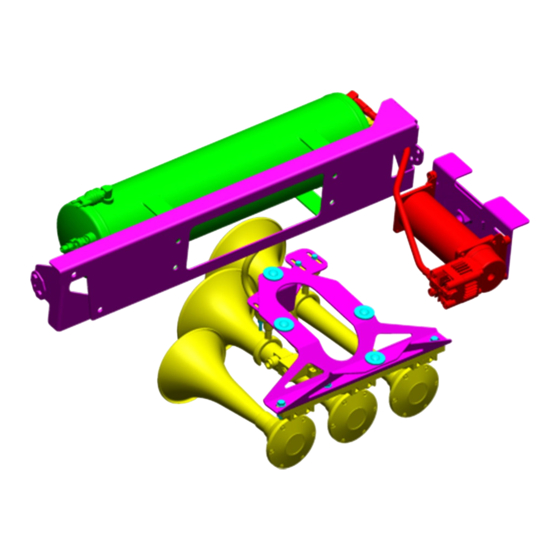
SDKIT17-230/734STD Installation and Operation Manual 5. Installation Overview 5.1. Kit Layout and System Location(s) SDKIT17-230/734STD consists of following components, located on vehicle, as follows: ITEM DESCRIPTION VEHICLE LOCATION MOUNTING APPROX. METHOD INSTALL TIME 6450RC Air Compressor Underbody, Passenger Side Bracket bolts to Frame 2-4 Hours ***OBA Kit (near Spare Tire) - Page 10 SDKIT17-230/734STD Installation and Operation Manual Figure 2 – Under Vehicle View of Air Horn Installed – without Air Tank & Compressor (2017 F-250 Shown) Go to Table of Contents PG 10/30 REV: BETA (4/13/2020)
-
Page 11: Install Process Outline
SDKIT17-230/734STD Installation and Operation Manual 5.2. Install Process Outline For person(s) with prior experience installing SDKIT17-230/734STD, a reminder of install steps are listed below: UNPACKAGE KIT (SECTION 1. Layout and organize all parts on bench BENCH ASSEMBLY (SECTION 2. Remove Air Horn Trumpets from Air Horn sub-assembly ON-VEHICLE, MECHANICAL (SECTION 3. -
Page 12: List Of Tools And Supplies
SDKIT17-230/734STD Installation and Operation Manual 6. List of Tools and Supplies 6.1. Standard Tool List (Required) 6.1.1. Basic mechanic’s 3/8” drive socket sets with extensions • Inch Size Sockets (1/4” – 1” Hex) • Metric Size Sockets (6mm – 20mm Hex) 6.1.2. -
Page 13: Parts List
SDKIT17-230/734STD Installation and Operation Manual 7. Parts List 7.1. Before Starting, Review Parts List Unpackage and organize Kit across a large work area and verify all parts are included, as listed below. Contact Kleinn support if any questions arise. 7.1.1. Review pre-packaged Kit items (i.e., K1, K2, etc.) 7.1.2. -
Page 14: Air Fittings And Related Items
SDKIT17-230/734STD Installation and Operation Manual 7.3. Air Fittings and Related Items ITEM PART NUMBER DESCRIPTION PICTURE 51238L 3/8” NPT X 1/2” Compression Fitting, 90 Deg Elbow 53814R 3/8” NPT FEMALE X 1/4” NPT (230STD ONLY) Reducer Fitting 51414L 1/4" NPT X 1/4" TUBE FITTING, (230STD ONLY) MALE 90 DEG. -
Page 15: Electrical Small Components And Related Items
SDKIT17-230/734STD Installation and Operation Manual 7.4. Electrical Small Components and Related Items ITEM PART NUMBER DESCRIPTION PICTURE SD17-STD WIRE KIT ELECTRICAL WIRE, CONNECTORS, AND ZIPTIES • PURPLE (18 GA.) – 20 FT • BLACK (12 GA.) – 2 FT SD17-STD LOOM WIRE LOOM, CORRUGATED AND PACK SPLIT... -
Page 16: Hardware, Fasteners And Soft Parts
SDKIT17-230/734STD Installation and Operation Manual 7.6. Hardware, Fasteners and Soft Parts NOTE: Pictures only indicative, not to scale and may not represent exact item ITEM QTY. DESCRIPTION WHERE USED PICTURE (5/16"-18 X 1.00" LONG) HORN BRACKET MOUNTING (4) RIBBED NECK CARRIAGE BOLT, GRADE 2, ZINC-PLATED (5/16”... -
Page 17: Bench Assembly
SDKIT17-230/734STD Installation and Operation Manual 8. Bench Assembly Complete following steps off vehicle to facilitate final installation. 8.1. Disassemble Trumpets from Air Horn Drivers NOTE: This step is performed to facilitate installation on Vehicle of Air Horn sub-assembly, specifically in connecting Air Tubing, Wiring, and Horn Ore Supports (734STD only). -
Page 18: On-Vehicle Mechanical Assembly
SDKIT17-230/734STD Installation and Operation Manual 9. On-Vehicle Mechanical Assembly Complete following steps on-vehicle using a lift, vehicle ramps, or other safe lifting method. DANGER: Follows all manufacturer’s instructions for safely lifting vehicle; reference owner’s manual. 9.1. Remove Spare Tire Lift Mechanism 9.1.1. - Page 19 SDKIT17-230/734STD Installation and Operation Manual 9.1.4. Remove two (2) OE Bolts holding Lift Mechanism to Crossmember (see “HS1” in above image), then twist Mechanism counterclockwise to remove from Crossmember and lift out of Vehicle. Retain all parts for future use, if desired. Remove two (2) bolts Figure 5 –...
-
Page 20: Install Air Horn Bracket (Sd17-304)
SDKIT17-230/734STD Installation and Operation Manual 9.2. Install Air Horn Bracket (SD17-304) 9.2.1. Using Hardware #H1, H2, H3, H4, & H5 install Brackets onto Spare Tire Crossmember, as shown below. It is recommended to apply medium-strength Loctite to Bolts and final torque to 75 in-lbs. NOTE: Initially install Large Bracket -304 using only two (2) bolts, to facilitate alignment with other bolts. -
Page 21: Install Air Horn Ore Support Bracket (Sd17-306) - 734Std Only
SDKIT17-230/734STD Installation and Operation Manual 9.3. Install Air Horn Ore Support Bracket (SD17-306) – 734STD ONLY 9.3.1. Remove front most nut, lock washer, and flat washer, then install Support Bracket, as shown below; ensure it is correctly oriented. Re-install hardware and final torque to 75 in-lbs. NOTE: This step is excluded from 230STD Plastic Horns, as they do not include Horn Supports. -
Page 22: Install Air Horn Sub-Assembly
SDKIT17-230/734STD Installation and Operation Manual 9.4. Install Air Horn Sub-Assembly 9.4.1. Using Hardware included (*) inside of Horn Packaging, install Air Horn sub-assembly onto Bracket, as shown below then final torque to 75 in-lbs. 9.4.2. Using Hardware included (*) inside of Horn Packaging, install Horn Support Ore Locks, as shown below. Finger tighten hardware on Ore Locks at this time. -
Page 23: Install Air Tank Fittings On Air Tank & Connect Air Tubing
SDKIT17-230/734STD Installation and Operation Manual 9.5. Install Air Tank Fittings on Air Tank & Connect Air Tubing 9.5.1. If Air Tank is already installed in vehicle, it may be required to remove Air Tank to gain enough space. 9.5.2. If Air Tank has not been installed yet, assemble Fittings during bench assembly. 9.5.3. -
Page 24: Final Trumpet Installation
SDKIT17-230/734STD Installation and Operation Manual 9.6. Final Trumpet Installation 9.6.1. Re-attach Trumpets to Air Horn Drivers, as shown below. Ensure Trumpets are firmly tightened by grasping Metal/Chrome Collar, as performed earlier. 9.6.2. On 734STD, apply light grease or Vaseline to inside rubber face on Ore Locks, then insert Trumpets through Ores and tighten firmly. -
Page 25: On-Vehicle Electrical Installation
SDKIT17-230/734STD Installation and Operation Manual 10. On-Vehicle Electrical Installation CAUTION: Follow all recommended safety precautions for working on vehicle’s electrical system; consult vehicle owner’s manual for further instruction. 10.1. Relay and Fuse Diagram for Air Horn System Figure 12 – Suggested Ignition Relay Diagram for Air Horn System (230/730 Horn Shown) Go to Table of Contents PG 25/30 REV: BETA (4/13/2020) -
Page 26: Suggested Wire Routing For Air Horn System
SDKIT17-230/734STD Installation and Operation Manual 10.2. Suggested Wire Routing for Air Horn System FRONT Figure 13 – Suggested Wire Routing for Horn, Air Compressor, and Pressure Switch (SDKIT17-734STD Shown) 10.3. Disconnect Vehicle Battery(s) 10.3.1. Consult Owner’s Manual. 10.4. Connect Wiring to Fuse and Relay 10.4.1. -
Page 27: Install Horn Button
SDKIT17-230/734STD Installation and Operation Manual 10.5. Install Horn Button 10.5.1. Find a suitable location for Horn Button (i.e., in dash, center console, etc.); verify location has 1”+ of clearance behind for terminal connectors. Mark location for drilling. 10.5.2. Drill a 3/4” hole at location. Route Horn Button wires to hole then slide push-button retaining nut over wires and connect wiring. -
Page 28: Final Steps & Testing
SDKIT17-230/734STD Installation and Operation Manual WARNING: NEVER operate train horns with ears 11. Final Steps & Testing close to trumpets or in an enclosed space 11.1. Reconnect Vehicle Battery(s) without substantial hearing protection (i.e., > CAUTION: Before connecting vehicle battery(s), Ear Plugs and Ear Muffs) for all persons closer verify all wiring is properly connected and no shorts than 100 feet from vehicle. -
Page 29: General Operation
SDKIT17-230/734STD Installation and Operation Manual 13.1. Yearly, or every 12000 miles verify all 12. General Operation mounting fasteners are properly torqued; 12.1. Compressor Operation applying witness marks across fasteners and mounting parts is good practice to quickly WARNING: NEVER operate Air Compressor ensure fasteners have not moved. -
Page 30: Warranty Information
Thank you for purchasing SDKIT17-230/734STD. Shall you experience any unexpected problems during installation or have problems with any part at any time please contact Kleinn support. End of Technical Manual © Kleinn Air Horns 2020, All rights reserved. PO Box 91278 Tucson, AZ 85752 Phone: (520) 579-1531 Web: www.Kleinn.com...
Need help?
Do you have a question about the SDKIT17-230STD and is the answer not in the manual?
Questions and answers