Advertisement
Quick Links
Advertisement

Related Manuals for Jema JM-988


Summary of Contents for Jema JM-988
- Page 1 INDUSTRIAL SEWING MACHINE...
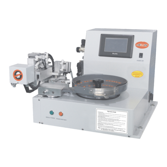
- Page 2 I.Overview Automatic button feeding device is composed of feeding identification mechanism, pneumatic button transmission mechanism, button rotating and falling mechanism, thickness measuring mechanism, gate adjusting mechanism, mechanical arm button feeding device, thread loosening mechanism, as well as mechanical, electrical and gas part and control mechanism.
- Page 3 “Quantity”: It shows the current quantity; the quantity will be reset after pressing this key. Quantity In/Output “Output/input indicator light”:Display the working indicator lights of all systems by pressing this key. Indicator light “Button feeding control/Vibration Controller”:Set the time of vibration, gear of vibration and speed Vibration of button feeding by pressing this key.
- Page 4 “Moving up and down of vertical shaft”: The vertical shaft will move down after pressing this key and Vertical the vertical shaft will move up after pressing this key again. Shaft Up&Down “Taking button by operating button clamp”: Button clamp will be unfolded after pressing this key and To Clamp the button clamp will be folded after pressing this key again.
- Page 5 V. Introduction to Basic Operation 1.Start-up operation: 1.Check whether there are tools or foreign objects around the machine. 2.Connect to the gas source, adjust the pressure and ensure the value of pressure gauge is between 0.3-0.35Mpa. 3.After turning on the power, the button indicator lights at the panel will become green and function interfaces will be displayed on the touch screen.
- Page 6 3. When change buttons, in order to feeding buttons correctly, according to the different size of button’s diameter to adjusting the J1 sensor position. (as shown in Fig.5) Fig.5 4.Conntect to the total intake air supply, adjust the pressure of gas pressure meter to be between 0.35-0.4Mpa. (as shown in Fig.6) Fig.6 5.After pressing the power switch, the power indicator light will be on (as shown in Fig.7), the touch screen will...
-
Page 7: Important Note
7.Press the key “Manually Feeding button”, check whether the specifications of button gripper base are appropriate, and replace it if the specifications are not appropriate. 8.Press the key “Manual testing” and then “Stretching out and drawing back of damper”. Stretch out the gate, and adjust the gap between buttons to be 0.2-0.5MM. - Page 8 4. Support second time thread trimming function: Support button sewing machine second time and one time thread trimming function VI. Button Sewing Operations: Conduct Operations according to the instructions of button sewing machine. VII. Troubleshooting 1.Buttons do not fall to the proper position Solution: 1.Check the position of magnetic switch 2.Check the central position of rotating column and button feeding needle plate...
- Page 9 Button sewing machine(JUKI type):1900 and 1903 series Proper position for installation of sensor fixing support Fig.1 Before the button feeder machine sensor is installed Fig.2 After the button feeder machine sensor is installed Installation method: Take the white fastener out of the machine (Fig.1), Adjust the trimming rod to the lowest level.
- Page 10 Brother products: 438HS Series Installation Position of Sensor Fixing Support Fig.6 Installation Position of Button Sender Sensor Installation method: The red circle with the corresponding position of the first punch ,bottom out the trimming connecting rod, install button attaching machine sensor in screw hole, adjust the sensor and connecting rod until the spacing is 0.5mm (sensor light is on), as shown in Fig.
- Page 11 JACK (JACK) all-in-one machine JACK (JACK) all-in-one machine Installation Position of Induction Fixing Support Installation Position of Induction Fixing Support Fig. (9) Before Installation Fig. (9) Before Installation Fig. (10) Before Installation Fig. (10) Before Installation Fig. (11) After Button Sender Sensor Installation Fig.
- Page 12 Fig. (13) After the Sensor Installation Fig. (14) After the Sensor Installation Installation method: Dismantle the shell behind button attaching machine (Fig. 12), fix the sensor on button attaching machine until sensor light is on (Fig. 13) and sensor is not touched by trimming iron (Fig.
-
Page 13: Installation Method
Fig.20 After the 373D sensor is installed Fig.19 After the 373D sensor is installed Installation method: Installation method: Before installing, find out the trimming electromagnet of the button attaching machine Fig. 17, then push the wire aside, connect the button feeding sensor of the feeder with the wiper signal cable, then insert jack. - Page 14 Installation position of J28 broken needle protection sensor (protect button attaching machine) Dahao system Heavy machine (JACK, brother and ZOJE) Installation method( Dahao system (JACK, brother and ZOJE ) Connect J28 broken needle protection sensor to the pedal switch wire of button attaching machine, shear off one red wire of pedal switch, connect one end with that of J28 sensor and link up another end with corresponding wire of J28 sensor (Dahao system).
Need help?
Do you have a question about the JM-988 and is the answer not in the manual?
Questions and answers