Table of Contents
Advertisement
Quick Links
Advertisement
Table of Contents

Summary of Contents for DINTEK 6202-01001
- Page 1 MAIN INDEX Handheld Optical Power Meter DINTEK Handheld Power Meter Manual...
- Page 2 MAIN INDEX Handheld Optical Power Meter Safety Sign: When using the optical power meter, always take bask safety precautions to reduce the harm for the testers, and injury to persons. All the safety sign may not mark in this manual. Warning:Prohibited misconduct and operation, to prevent any improper conduct and operation of the damage.
-
Page 3: Table Of Contents
MAIN INDEX Handheld Optical Power Meter Contents Chapter 1. Standard Configuration……………..……………………………….1 Chapter 2. Overview…….……………………...……………...…………………..1 Chapter 3. Data Sheet……….……………………………………………..……...2 Chapter 4. Function………….………….……………………………..………..3 4.1 Front…………………………………………………..……………………………….3 4.2 Two Sides…………………………………………………………………..…………6 Top…………………………………………………………….……………..…………8 Backside……………………………………………………………………………….9 Chapter 5. Software..…………………………………...….…………………..….10 5.1 Install the device……………………..……………….………………………….….10 5.2 Install the application software……………………………………………………..14 5.3 Software function instruction……..…………………………………………….…..15 Chapter 6. -
Page 4: Chapter 1. Standard Configuration
Cotton Swabs Carry Bag Chapter 2: Overview The DINTEK Handheld Optical Power Meter is a newly designed fiber optic tester, aimed at the installation of fiber, engineering acceptance and maintenance of fiber networks. Compared to usual power meters, the DINTEK Power Meter has additional functions, like automatic wavelength identification, auto wavelength switching, intelligent backlight and data saving via USB port. -
Page 5: Data Sheet
MAIN INDEX Handheld Optical Power Meter Chapter 3: Data Sheet Model Calibration Wavelength(nm) 850/1300/1310/1490/1550/1625 Detector type InGaAs Measurement Range(dBm) -70~+6 -50~+26 Uncertainty (dB) ±0.15(3.5%) linearity (dB) ±0.02 Display resolution(dB) 0.01 Frequency ID(Hz) 270,330,1K,2K Wave ID(nm) 850,1300, 1310,1490,1550,1625 Date Storage Capacity 1000 Communication Port Standard Connector... -
Page 6: Function
MAIN INDEX Handheld Optical Power Meter Chapter 4: Function 4.1 Front (10) Power Key Turns the instrument ON/OFF. Power Saving setting: Under power saving, the unit will automatically shut off after 15 minutes idle time, whatever the condition of battery power supply or AC power supply. Once selecting this setting, the “auto-off”... - Page 7 MAIN INDEX Handheld Optical Power Meter Wavelength Selection/Wavelength identify Short press this key to switch the wavelength and display it on the top left of the LCD screen, 1310nm is the default wavelength. Calibrated wavelength Press the for 2 seconds to on/off the wavelength auto-identify mode. On the upper right of the screen wil be displayed the letters “AU.
- Page 8 MAIN INDEX Handheld Optical Power Meter 0008 …… 0001 Delete/Cancel Key. 1. Data Delete. When viewing specific data, press to delete the record. 2. Cancel the saving. When in the saving mode, press to cancel the current data saving. Unit switch key Press the Unit key to switch between the absolute measurement(dBm) and relative measurement(dB) and nW of the optical power.
-
Page 9: Two Sides
MAIN INDEX Handheld Optical Power Meter REF setting: To store the current power value as the reference value which will be displayed on the top right of the LCD screen, at the same time the “Ref” also display on the right top. It will compare the current power with the reference power and show the relative power value in dB. - Page 10 MAIN INDEX Handheld Optical Power Meter 4-2left side 4-3 right side (1) Power Supply unit port Used for connecting with the AC adaptor (pic. 4-4) AC adaptor Notice: Please use only the power supply unit supplied with the tester. Use of other kinds of PSU may cause damage to the instrument.
-
Page 11: Top
MAIN INDEX Handheld Optical Power Meter 4.3 Top (1)Dust Cap In order to protect and avoid damage to the optical connector, when not in use make sure that you place the dust cap over the connector. (2)Optical Connector The standard of this power meter connector a PC & Φ2.5mm universal connector. pic. 4-7 & 4-8. Screw off the FC connector, and it will turn into a Φ2.5mm universal connector. -
Page 12: Backside
MAIN INDEX Handheld Optical Power Meter Cotton Swab 4-10 4.4 Backside 4-11 (1) Label Content includes the function of, and the instrument information (2) Bracket Collapsible metal bracket, 0~90 degree can be adjusted. (3) Battery Pack This unit takes 3 x 1.5v AA batteries. Notice: When inserting the batteries, take a note of their positive (+) and negative (-) connector orientation, the negative battery connector should be against the spring. -
Page 13: Chapter 5 Software
MAIN INDEX Handheld Optical Power Meter Chapter 5 Software 5.1 Install the device Run the software in the PC, find the “CH341SER-CH340T” as shown below Double click that “exe” program. This will initiate program. See fig. 5-1 Click “INSTALL”. after you will see the following, Fig 5-2 Press “OK”, to exit this install interface. - Page 14 MAIN INDEX Handheld Optical Power Meter Press “NEXT”, See Fig. 5-4 Fig. 5-4 After driver install, click FINISH to exit,See Fig. 5-5 Fig. 5-5 To check if the installation is complete and to avoid any communication problems, when the power meter is connected with the P, open the “Device Manager”...
- Page 15 MAIN INDEX Handheld Optical Power Meter Fig. 5-6 Fig. 5-7 After successful install of the device, you can switch off the power meter and disconnect the USB cable. 5.2 Install the application software Run the CD in the PC, find the “setup” file Double click this icon,See Fig.
- Page 16 MAIN INDEX Handheld Optical Power Meter Fig. 5-8 Press “Next”, (as per Fig. 5-9) Fig. 5-9 Choose “I accept ……”, Click “Next” (as per Fig. 5-10) Fig. 5-10...
-
Page 17: Install The Application
MAIN INDEX Handheld Optical Power Meter Choose “I accept ……”, click “Next”, (as per Fig. 5-11) Fig. 5-11 Click “Next”, (as per Fig. 5-12) Fig. 5-12 Fig. 5-13... -
Page 18: Software Function
MAIN INDEX Handheld Optical Power Meter Click “Finish”, Complete the installing (as per Fig. 5-13) 5.3 Software function instruction This software has two functions: data processing, and the setting the instrument. After finishing the software installation, find the short cuts icon for this software. Double click this icon to open the software. - Page 19 MAIN INDEX Handheld Optical Power Meter III. Language option, Drop-down the manual, Find the right language for the user prefer, Chinese/ English. IV. Function interface option: Two functions for option--data processing and the instrument setting, drop-down the manual to choose. V.
- Page 20 MAIN INDEX Handheld Optical Power Meter III. Delete all the data that saved in the instrument. (5) Data display area To display the saved data of the instrument 5.3.2 Power Meter setting Fig. 5-15 Power Meter setting interface, pic. 5.3.2,which include 4 parts: (1) Menu bar(Please refer description in data process interface)...
-
Page 21: Chapter 6. Operation Instruction & Notes
MAIN INDEX Handheld Optical Power Meter Chapter 6 Operation Instruction and Notes 6.1 Powering the Optical Power Meter The optical power meter can be either battery powered or AC adaptor powered, giving total flexibility for most testing sites and situations. 6.1.1 AA battery When using AA batteries, will display on the left top of the screen,(as per Fig. -
Page 22: Power On The Optical Power Meter
MAIN INDEX Handheld Optical Power Meter Notice:Make sure that you insert the batteries with their positive and negative connectors correctly aligned. 6.1.2 Power Supply Unit When the battery is used out, can use the power supply unit, and at this time on the left top of the screen, there will be a (as per Fig. -
Page 23: Meter
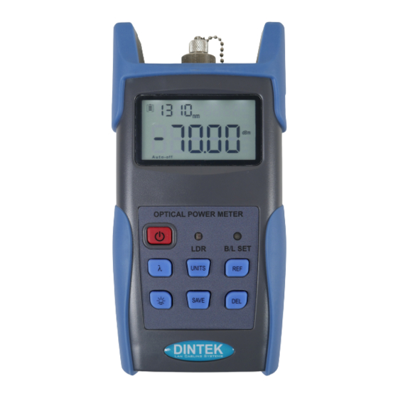
MAIN INDEX Handheld Optical Power Meter 6.2 Power On the optical power meter First, insert the battery or the PSU. Press to turn on the tester, (Fig. 6-5) is the opening interface. Electricity Indicator Calibrated dBm Value Power saving mode (Auto-off) Fig. -
Page 24: Output Power
MAIN INDEX Handheld Optical Power Meter 6.4 Output power measurement 6.4.1 Take off the dust cap, connect with the patch cord. Notice: Make sure the connector and the end-face of the patch cord is clean and take notice on the type of the patch cord, make sure the correct patch cord is connected. -
Page 25: Data
MAIN INDEX Handheld Optical Power Meter 6.4.4 Relative value measurement Each wavelength can set the Ref value, Press ,set the current value as the ref value, and automatically calculate out the relative value. (Right top of the screen display the “ref” and setting dBm value 6-10) Relative value setting Relative value setting... - Page 26 MAIN INDEX Handheld Optical Power Meter 6.5 Data Communication Note Before initiating the data communication, make sure the driver and application software are installed : successfully (For details of installation please refer to chapter 5) 6.5.1 Opening the software Double click the icon to open the software.
- Page 27 MAIN INDEX Handheld Optical Power Meter Therefore, choose “COM4”port shown as below as per figure (6-15) Fig. 6-15 Next click “Connect” as shown in below figure 6-16. This will pop up a successful connection window shown as 6-17, click “OK” to finish the connection, the unit will now be communicating with the PC. Fig.
- Page 28 MAIN INDEX Handheld Optical Power Meter 6-19 Data editing is done in the data display area, including data delete, data save and data printing. Select the required data, click “delete one” to delete it from the sheet, as shown on figure 6-20 and figure 6-21, in addition, The corresponding data from the power meter also will be cleared accordingly.
- Page 29 MAIN INDEX Handheld Optical Power Meter 6-21 Click “Delete all” which will show a pop up a window shown as figure 6-22, click “OK” to delete all data, also will clear all saved data from the unit. 6-22 Click “Save” pop up a window shown in figure 6-23, input the file name, choose the save path and press “ok”...
- Page 30 MAIN INDEX Handheld Optical Power Meter Fig. 6-24 Click when in the software,you can print testing report directly, you can also print the testing report from Excel. 6.5.3 Function setting on the unit Under the function setting mode, you can switch the interface as shown on figure 6-25 and figure 6-26: Fig.
-
Page 31: Wavelength Automatic Identification
Click exit,pop up a window shown as below (figure 6-30): 6-30 6.6 Wavelength Automatic Identification Connect power meter with a DINTEK Optical Light Source Unit. Enable light source to be set under “Wave ID” operation mode: press of light source to ... -
Page 32: Frequency Detection
MAIN INDEX Handheld Optical Power Meter 1310nm(xxdBm) 1310nm(xxdBm) 1550nm(xxdBm) 1550nm(xxdBm) …… …… MATCHED Light Source Power Meter Fig. 6-31 6.7 Frequency detection Note: When use tone detection function, following requirements have to be taken into account: For A: Tone detection will be effective only with measurement range between +6~-40dBm. For C: Tone detection can be worked only with measurement range between +26 -20dB, because the detected ~... -
Page 33: Power Off
MAIN INDEX Handheld Optical Power Meter Note Frequency ID and wave ID cannot be operated at the same time. : To avoid risk of serious eye damage, please do not look into the optical port of laser source at any time. 6.8 Power off Automatic power off: When auto-off function is activated, the unit will turn itself off automatically after 10minutes idle time, whatever the power supply is with alkaline batteries or is with power supply adaptor... -
Page 34: Quality Warranty
Such as artificial damage, or operating in abnormal conditions of like high temperature、high voltage, humidity and etc., we will charge depend on the actual failure rating. DINTEK Electronic Limited 5F., No.8, Ln. 97, Wugong Rd. Xinzhuang Dist., New Taipei City 242 Taiwan (R.O.C.)
Need help?
Do you have a question about the 6202-01001 and is the answer not in the manual?
Questions and answers