Advertisement
Quick Links
Advertisement

Subscribe to Our Youtube Channel
Summary of Contents for VideoSystemer VSDT-315
- Page 1 Apartment Villa Intercom Access VSDT‐315 User Manual Ver 1.0 Download APP ...
-
Page 2: Product Features
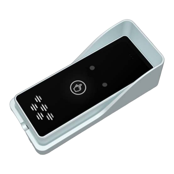
1. Product features ◆ Support 200 sets of numbers, each number can be set in the time period to control the relay to open the door. ◆ A relay output is used to control to open the door, connected when there is the number of incoming users , And it will automatically disconnect at set time. ◆ After a user calls to control to open the door, it can send SMS to the user about its action. ◆ 000~999 seconds, we can control the relay closing time, 000 indicates: the relay is closed for 0.5 seconds then disconnected. 999 indicates: the relay can be closed until the same number incomes again then disconnected. ◆ SMS commands can be used to query the current state of the host (relay status and GSM signal value). ◆ SMS can be regularly uploaded for the current state of the host to the first user number. ◆ Use the clock on the module, each time the host sends SMS to itself to correct the time. 2. Host overview Microphone Relay, door indicator lamp (Closed: light, disconnected: out) Signal lamp GSM version: Slow flash means normal signal. Fast flash means searching signal. No light means no signal. 3G version: When the signal is normal, the light goes out 1 time per second. When ... -
Page 3: Setup And Operation
Internal wiring instructions 3. OUTX (White Wire): The output of the relay is connected with the electromagnetic switch, used to control the door. PJ1 (Red and Black Wires): External power supply, the use of 9‐24VDC, pay attention to distinguish between positive and negative (Red Wire: Positive, Black Wire: Negative). RST: Reset, jumper wire connection, and then boot, after 10 seconds, disconnect, Restore factory settings (reset does not clear user’s number information). J4 (Yellow Wire): Connect to door switch. 4. Setup and operation This device is set up and operated by SMS. All of the following letters are uppercase letters. Password factory default is 1234, "+" is not the message content, Such as equipment time command: 1234TEL13812345678#. Each instruction will receive the corresponding information or action of the feedback from the device. If you do not receive ... - Page 4 ◆ Query user number authorization time Password + A + serial number# ◆ Query user number Password + AL + serial number# + serial number# Example: 1234AL001#009# (query user number of 001~009) ◆ Set allows any number of incoming to control relay Password + ALL# ◆ Set only user number available of incoming to control relay (default) Password + AUT# ◆ Set relay closing time Password + GOT + the closing time# Closing time is 000~999, Unit: second The closing time is set to 000 (default), which means that the user will automatically disconnect when the relay is closed for about 0.5 seconds; The closing time is set to 999, which means that the relay is closed until the same number is called in again. ◆ Set whether or not to return SMS after the relay is closed 1) Set to return SMS to the first number and the incoming number after the relay closing (default) Password + GON11# + Content of SMS# 2) Set to return SMS to the first number, not to the incoming number after the relay closing Password + GON10# + Content of SMS# 3) Set to return SMS to the incoming number, not to the first number after the relay closing Password + GON01# + Content of SMS# 4) Set not to return SMS after the relay closing Password + GON## ◆ Set whether or not to return SMS after the relay disconnecting. 1) Set to return SMS to the first number and the incoming number after the relay disconnecting (default) Password + GOFF11# + Content of SMS# 2) Set to return SMS to the first number, not to the incoming number after the relay disconnecting. Password + GOFF10# + Content of SMS# 3) Set to return SMS to the incoming number, not to the first number after the relay disconnecting. Password + GOFF01# + Content of SMS# ...
- Page 5 4) Set not to return SMS after the relay disconnecting. Password + GOFF## ◆ SMS control relay closed Password + CC ◆ SMS control relay off Password + DD ◆ Query device status Password + EE ◆ Set interval reporting time Set the fixed interval to report the current state of the device to the first number: Password + T# + Interval time# Interval time : 000~999,unit: hour,Default 000, it means not to report. ◆ Query interval reporting time Password + T# ◆ Query module IMEI code and firmware version number Password + IMEI# 5. Schedule: SMS instruction set Function SMS command Remarks Equipment time calibration Password + TEL + equipment number# The first time or replace the phone card. That needs it. ...
- Page 6 Return SMS after relay closing Password + GON + ab# + SMS content# a, b=0 or 1; (a corresponds to the first number, b corresponds to the Return SMS after relay Password + GOFF + ab# + SMS content# number of incoming calls, 0: not to disconnecting return, 1: to return) Not to return SMS after relay Password + GON## closing ...
Need help?
Do you have a question about the VSDT-315 and is the answer not in the manual?
Questions and answers