Table of Contents
Advertisement
Quick Links
Advertisement
Table of Contents

Summary of Contents for SST NR-900S
- Page 1 PORTABLE NONLINEAR JUNCTION DETECTOR “NR-900S” User manual - 2018-...
- Page 2 PORTABLE NONLINEAR JUNCTION DETECTOR “NR-900S” User manual - 2018-...
-
Page 3: Table Of Contents
NR-900S Operation Manual CONTENTS Application.…………………………………. NR-900S complete set………………………. Main technical parameters…………....Function ……………………… Design ……………………………....Main unit ………………………….… Control unit ……………………………..Accessories ……………………………..… Imitator ……………………… Headphone NR-900S power supply…………………….…. Charger ……………………………. NR-900S operation Operation condition and restriction Getting started NR-900S workability test... - Page 4 NR-900S Operation Manual This Manual is intended for explanation “NR-900S” Non-linear Junction Detector design & principle of operation as well as directions for its use. For proper equipment use, study this Manual in depth.
- Page 5 Radio Communication Regulations of the country where ‘NR-900S’ NLJD is being used It is highly recommended not to aim the device antenna to any human body or pets from the distance less than 1 meter...
-
Page 6: Application
Fig. 1 NR-900S devices (IED) and etc. NR-900S can detect typical targets in every operational mode: active, stand-by or even switched-off. NR-900S ensures comprehensive searching capabilities and reliable localization of ‘bugs’ in fabric constructions, furniture and various office or home items. -
Page 7: Nr-900S Complete Set
NR-900S Operation Manual 2. NR-900S COMPLETE SET (fig. 2) Fig.2 NR-900S Complete set Table 1 NR-900S main unit Carry case Headphones Car power adapter Soshine SC-S1 battery charger AC power adapter Target imitator (test unit) Soshine 18650 rechargeable cells Operation manual (not shown) -
Page 8: Main Technical Parameters
NR-900S Operation Manual 3. MAIN TECHNICAL PARAMETERS Table 2 Average probing signal power in Searching not less 400 mW mode Maximal probing signal pulse power in not less 2 W Searching mode Maximal probing signal continuous power in not less 2 W... -
Page 9: Function
The receiver inputs switching as well as headphones volume control is available from the device control panel. NR-900S has three output levels for radiated probing signal with 6 dB step and four levels of the receiver input signal attenuation each of 10 dB. -
Page 10: Design
NR-900S Operation Manual 5. DESIGN MAIN UNIT NR-900S main unit (see also fig.3) represents a mono-block that consists of antenna system and electronic unit: transmitter with two receivers, control module and LED display - indication panel. Fig. 3. NR-900S ready for operation. 1-main unit, 2- control unit with display, 3 -headphone, 4 –... -
Page 11: Control Unit
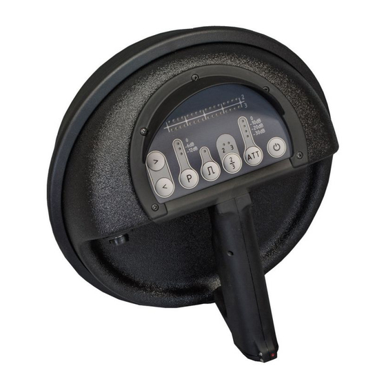
On the back side of the main unit the Control unit with a handle and operation display are placed. NR-900S is made in dust- and waterproof version and has robust enclosure, ensuring safe operation within wide range of temperatures. CONTROL UNIT Fig.4 NR-900S Control unit with display... -
Page 12: Accessories
The jack for headphone connection is on the left side of the device body (pos. 4 at the fig.3). 6. ACCESSORIES IMITATOR Target Imitator (test unit) is intended for NR-900S workability control (fig. Imitator represents high-frequency semi- conductor diode in a solid Fig. 9 NR-900S Imitator (test unit) plastic body. -
Page 13: Headphone
Fig. 10 Headphone NR-900S POWER SUPPLY NR-900S power supple is provided by the battery of two Li-Ion rechargeable cells -18650 form factor (fig. 11). Cell rated voltage is 3.7V with 2800mAh capacity. -
Page 14: Charger
Soshine SC-S1 max Charger (fig. 12) is intended for rechargeable cells charging. The battery charging is performed in an automatic mode and does not need any operator’s assistance. Fig. 12 NR-900S standard Charger complete set. 1 – Soshine SC-S1 max charger unit 2 – Soshine DС 12V car adapter 3 –... -
Page 15: Nr-900S Operation
Operating NR-900S keep corresponding safety measures. Safety precautions for open RF emitters: - Do not direct NR-900S antenna to the human eyes from the distance less than one meter. - Avoid prolonged presence of personnel in a main lobe of NR-900S antenna’... -
Page 16: Getting Started
NR-900S Operation Manual GETTING STARTED Take NR-900S components out of standard packing. Insert two fresh rechargeable cells (fig. 12) into the battery compartment keeping the cells polarity specified on the compartment side wall . Watch cells polarity Fig. 13 Inserting rechargeable cells - Close the battery compartment cover and lock it. -
Page 17: Nr-900S Workability Test
0.4 m antenna unit. Fig. 14 NR-900S operation test by means of standard imitator The interrupted audio signal should be heard in the headphone, as well as 6 red & 6 green LEDs shine at the corresponding bar-graph scales. -
Page 18: Nr-900S Safety Precaution
The device is fully functional and ready for operation. USEFUL HINT: An original schematic design enables to supply NR-900S operator with an outstanding feature: searching for illegal electronics the NLJD Operator takes notice of an audio alarm signal (tiny beep-beep) prior to custom LED indication. -
Page 19: Detector Operation In 'Listen' Mode
NR-900S Operation Manual DETECTOR OPERATION IN ‘LISTEN’ MODE Switch over Detector to the ‘LISTEN’ mode: LED is off. Direct the device to the possible target position. Control the audio signal in the headphone switching the button 2/3 to obtain the 2 and the 3 harmonic reply. -
Page 20: Packing
NR-900S Operation Manual NOTE: The practical probing signal level and receivers sensitivity are defined by the interference environment right on spot of the operation. There might be certain outside signals on the receivers adjustment frequencies and/or the presence of nonlinear reflectors, that cannot be removed from the examination area. -
Page 21: Emergency Actions
NR-900S Operation Manual 9. EMERGENCY ACTIONS − In case of the equipment malfunction that cannot be corrected by the operator, Detector operation should be stopped. − If Detector exposed external mechanic, electromagnetic or climatic impact and temporarily lost its workability, then before restoring the operation it is required carry out its visual checks and functional test referring p. -
Page 22: Battery Charging
NR-900S Operation Manual 10. BATTERY CHARGING (fig. 15). Insert 2 or 4 cells (pos.3) into Soshine Charger chamber (if necessary slide ‘minus’ spring contact) Pay special attention to cells polarity referring indication on the charger chamber Couple AC power adapter or DC 12V car adapter to the socket on a side wall of the Charger (pos. - Page 23 NR-900S Operation Manual Charger LED indication (Fig. 15, pos.1) Table 5 Charging process status LED light mode Charger workability self -test 4 x LED light red then switch over to green Alter green to red Defective or cells of a wrong type...
- Page 24 NR-900S Operation Manual Charger operation precautionary measures - Do not try to charge primary cells! That can initiate an explosion and provoke the fire. Acceptable elements should have an inscription “Rechargeable”. - Do not block vent holes on the bottom of the charger housing.
-
Page 25: Maintenance
ATTENTION! IT IS FORBIDDEN TO DISASSEMBLE THE DEVICE! GENERAL INSTRUCTIONS The NR-900S maintenance should be carried out by the personnel who studied the Operation Manual and have practical experience of NLJD usage. To keep NLJD in fault-free and ready-to-use condition the following maintenance are provided: –... - Page 26 – charge the batteries; – perform the device workability test; – remove the batteries; – pack NR-900S components into the carry case. Scheduled maintenance – charge the batteries. ROUTINE REPAIR The defective device repair, adjustment and setting-up should be carried out by authorized personal at the Manufacturer’s...
-
Page 27: Shipping And Storage
80 % under +25°C NOTE: Rechargeable cells should be stored in a charged state 13. CERTIFICATE OF ACCEPTANCE Non-linear Junction Detector NR-900S serial No _____________ is in conformity with the main technical parameters and is accepted for use. -
Page 28: Warranty
NR-900S Operation Manual 14. WARRANTY NR-900S warranty period is 12 months from the date of sale. Manufacturer guarantees normal functioning of the device on the assumption of the following all requirements of this Manual by the User and in case of malfunction within the Warranty period Manufacturer will repair the device free of charge. - Page 29 NR-900S Operation Manual FOR NOTES _______________________________________________________ _______________________________________________________ _______________________________________________________ _______________________________________________________ _______________________________________________________ _______________________________________________________ _______________________________________________________ _______________________________________________________ _______________________________________________________ _______________________________________________________ _______________________________________________________ _______________________________________________________ _______________________________________________________ _______________________________________________________ _______________________________________________________ _______________________________________________________ _______________________________________________________ _______________________________________________________ _______________________________________________________ _______________________________________________________ _______________________________________________________ _______________________________________________________...
Need help?
Do you have a question about the NR-900S and is the answer not in the manual?
Questions and answers