
Summary of Contents for Sanden Vendo CDU-L R06A2B
- Page 1 Delivering CO solutions in commercial refrigeration SANDEN RETAIL SOLUTIONS CDU-L R06A2B 3 Phases 400V installation guide...
- Page 2 Modifiez le style du titre Table of content 1. Product specifications 2. Product diagram 3. Operation diagram 4. Installation instruction 5. Handling 6. Piping connection 7. Power supply connection 8. External ON/OFF control signal 9. Piping and vacuuming 10. CO₂ charging 11.
- Page 3 Modifiez le style du titre 1. Product specifications CDU-L...
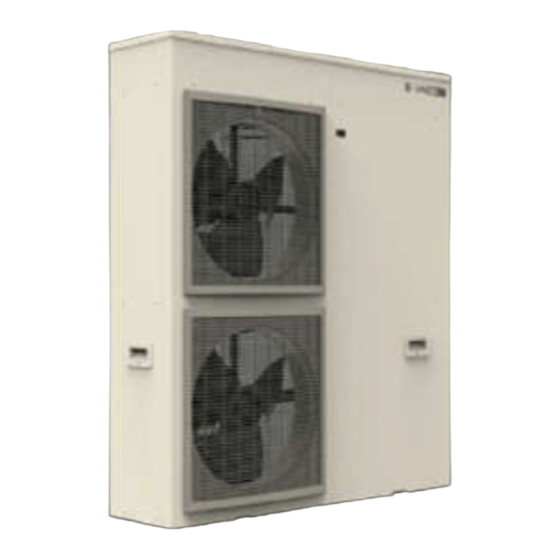
- Page 4 Modifiez le style du titre 2. Product diagram CDU-L...
- Page 5 3.1. Operation diagram: Modifiez le style du titre MT loop A&B MT A&B (Te -5℃ Tambient 10 ℃) Loop-A Loop-C Loop-B Loop-C (CHC) MT A&B (Te -5℃ Tambient 25 ℃) Loop-A Loop-C Loop-B Loop-A Loop-B (CLA) (CLB)
- Page 6 3.2. Operation diagram: Modifiez le style du titre LT loop A&B LT A&B (Te -30℃ Tambient 25 ℃) Loop-C (CHC) Loop -C Loop -A Loop -B Loop-A Loop-B (CLA) (CLB)
- Page 7 3.3. Operation diagram: Modifiez le style du titre LT loop A & MT loop B LT loop A & MT loop B Loop B Loop C Loop -C (CHC) Loop A Loop A Loop B (CLA) (CLB) Loop A: LT (Teva -30℃) Loop B: MT (Teva -5℃) Loop C: High stage compressor Ambient Temperature : 25℃...
- Page 8 Medium Temperature application : < 15dm3 (risk of poor lubrication if > 15dm3) Low Temperature application: < 5dm3 (risk of poor lubrication if > 5dm3) 3. Cooling capacity 4. Performance drop * Please follow SANDEN requirement to avoid performance drop and ensure good lubrication of the compressor.
- Page 9 Modifiez le style du titre 4.2. Installation condition 1. Installation conditions: Provide space above the equipment to allow it to be opened (access for maintenance / reparation operations). Provide at least 500 mm of free space on the right-hand side. Provide at least 500 mm of free space on the left-hand side and the front and back.
- Page 10 Modifiez le style du titre 4.3. Installation condition 2. Install the equipment in a dry and well-ventilated location, where air isn't recycled. 3. Place the equipment in a location sheltered from direct sunlight, heat sources and cold wind. If exposing the equipment to direct sunlight is unavoidable, protect the device with a canopy. 4.
- Page 11 Modifiez le style du titre 5. Handling When raising the refrigerating unit, always observe the following safety precautions: 1. Protect any parts that are in contact with hoisting ropes, e.g. using cardboard. 2. When the refrigerating unit is raised, do not go beneath it. 3.
- Page 12 Modifiez le style du titre 6.1. Piping connection Low-pressure equipment (Evaporator) 1. Pipe working pressure: Diameter MWP [bar] Discharge side HP 1/4" à 3/8" >120 bar Suction side LP 3/8" à 1/2" >90 bar 2. Pipe insulation mandatory 19mm for MT application ...
- Page 13 Modifiez le style du titre 6.2. CDU-L connected to single evaporator Evaporator volume MT : < 15000cc ( if more risk of poor lubrication). LT: < 5000cc ( if more risk of poor lubrication). Remarks It’s not necessary to add expansion valve on evaporator because the CDU has is own expansion valve. Add just thermostat device with defrost control...
- Page 14 Modifiez le style du titre 6.3. CDU-L connected to several evaporators Remarks: Expansion valve for each evaporator. One Pressure sensor by loop. Evaporator volume: MT : < 15000cc ( if more risk of poor lubrication). LT: < 5000cc ( if more risk of poor lubrication).
- Page 15 Modifiez le style du titre 7. CDU-L power supply connection Communication Power supply Cabinet regulator Rated power 5,4kW Cooling demand on CLA & CLB , dry contact. Voltage 400V AC Frequency 50/60 Hz Electric consumption 5,5kW The alarm contact deliver AC 230V in case of error. Rated curent 8,5A Electrical power...
- Page 16 Modifiez le style du titre 8.1. External ON/OFF control signal System control logic 1. The cooling demand is managed by dry contact sent to the CDU (terminals CLA/CLB) see page 15 2. The speed of compressor controls the LP to reach the set point tuned by the installer (A02/B02) see page 25 3.
- Page 17 8.2. Electrical connection Modifiez le style du titre (Thermostat & 1 evaporator) Contact Contact Contact Defrost Supply thermostat CLA / CLB CDU-L Resistance...
- Page 18 8.3. Electrical connection Modifiez le style du titre (DANFOSS regulator & several evaporators) Mandatory to supply 1 of the AKVH during the ramp down of the CDU to avoid discharge pressure cut. AKVH control R14=01 (On/Off) Remarks : The contact of auxiliary relay KA… (NO) must be wiring in parallel on the CDU ( contact CLA or CLB )
- Page 19 Modifiez le style du titre 9.1. Piping and vacuuming process 1. Brazing connection pipe 1-1. Check that cabinet EEV is completely opened. 1-2. Before brazing, insert 2bar nitrogen gas flow into pipe for preventing deposition of any oxide film on the inner surface of the piping, and also avoid heating up service valve by wet towel cover etc.
- Page 20 Modifiez le style du titre 9.2. CDU connection to the evaporators 1. Remove process pipe 2. Insert pipe 3. Brazing pipe...
- Page 21 9.3. Service valves connection and Modifiez le style du titre handling 1.Untightened the protection caps 4.Service valve handling 2.Connect the CDU to the manifold Outlet Male G 3/8’’ Example of connexion Inlet G 3/8’’ female Outlet ¼’’ SAE 3.Untightened the compression packing...
- Page 22 Modifiez le style du titre 10.1. CO charging process Charging CO procedure 1. Check CO amount for each evaporator and piping volume from graph. (see page 23) 2. Set CO vessel on the weight scale, purge air inside charge tube, and 0 setting scale before charging. 3.
- Page 23 Modifiez le style du titre 10.2. CO₂ charging amount estimation Evaporator volume Example : for a Medium temperature application at -5°C of evaporating temperature with an evaporator volume of 10 litres & 15m A/R of piping 1/4 » & 3/8 » Calculation CO2 load = 2500gr + 150 gr = 2650 gr Piping length...
- Page 24 Modifiez le style du titre 10.3. Check operation value 1. High pressure target Target discharge pressure P_dis[℃] Ambient temperature T_amb[℃] 9.86 9.86 9.45 8.78 8.11 7.43 6.76 6.50 6.50 6.50 9.86 9.86 9.45 8.78 8.11 7.43 6.76 6.50 6.50 6.50 9.86 9.86 9.45...
- Page 25 Modifiez le style du titre 11.1. CDU parameters change process Entering each cycle parameter list(A, B, & C-parameter) 1. Press simultaneously 3 button “DOWN▼”, “UP▲”, and SET for 3 secs from normal display 2. ”CLA” blinking on display (A-parameter) 3. Press “DOWN▼” or “UP▲” if changing each parameter set as “CLB” or “CHC” 4.
- Page 26 Modifiez le style du titre 11.1. CDU parameters change process Entering common parameter list(P-parameter) 1. Press only right “SET”button for 3 secs from normal display 2. ”P00” blinking on display(P-parameter) 3. Press right button(SET) if moving other P-parameter(P01, P02, …) 4.
- Page 27 11.2. Change Parameters each evaporating Modifiez le style du titre temperature set point Parameter Unit Factory set Tev≧-5℃ Tev≧-10℃ Tev≧-15℃ Tev≧-20℃ Tev≧-25℃ Tev≧-30℃ Tev≧-35℃ MIN Low Pressure for Comp-ON A/B01 MIN Low Pressure (Low Pressure Cut) A/B02 Target Low Pressure A/B05 ℃...
- Page 28 Modifiez le style du titre 11.3. Reading parameters list...
- Page 29 11.4. CO properties 11.3 Propriétés thermodynamiques du CO Modifiez le style du titre Relation entre Pression et Température d’évaporation Pressure as function of evaporating temperature Densité Densité Enthalpie Enthalpie Entropie Entropie Point Temperature Pression relative Pression absolue Liquide Vapeur Liquide Vapeur Liquide Vapeur...
- Page 30 Modifiez le style du titre 12. First level of maintenance 1. Regular inspections 2. In case of dirt inside the CDU, clean the outdoor heat exchangers with soft brush or vacuum cleaner. 3. Water can be used in case of clogged heat exchanger. (Noted: CDU operation should be stopped when using water cleaning for heat exchanger) Error list and diagnostic : check product guide...
- Page 31 Delivering CO solutions in commercial refrigeration THANK YOU!
Need help?
Do you have a question about the Vendo CDU-L R06A2B and is the answer not in the manual?
Questions and answers