ABB V-Contact VSC Series Installation And Service Instructions Manual
Hide thumbs
Also See for V-Contact VSC Series:
- Installation and service instructions manual (40 pages)
Table of Contents
Advertisement
Medium voltage products
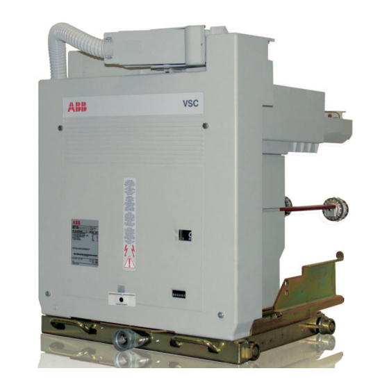
V-Contact VSC
Installation and service instructions
7.2/12 kV - 400 A
This instruction booklet refers to the following models:
VSC/F-VSC/FN-VSC/P-VSC/PG-VSC/PN-VSC/PNG
VSC-S/F-VSC-S/G-VSC-S/PG-VSC-S/PNG
1
2
2
3
3
3
3
4
4
5
6
6
8
8
9
9
10
11
12
13
14
14
14
14
14
15
21
30
33
34
34
35
36
36
36
37
38
NEPSI.COM - Northeast Power Systems. Inc.
38
38
39
40
43
43
43
44
44
44
Advertisement
Table of Contents


Need help?
Do you have a question about the V-Contact VSC Series and is the answer not in the manual?
Questions and answers